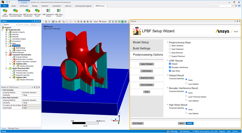
In the Postprocessing Options step:
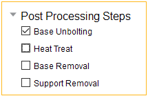
Select the post-build processing steps you want to simulate, such as base unbolting, heat treatment, and base and/or support removal. The default sequence for post processing will be base unbolting, heat treatment, support removal, and then base removal at the end, depending on which options are chosen. In the case of multiple supports, removal will be in the order that the supports were added. To reorder how the steps will be performed in the simulation, exit or finish out of the wizard and then modify the sequence directly in Mechanical using the AM Process Sequence worksheet.
Click Add Results to add standard result items to the project tree, specifically Temperature for a thermal system and Total Deformation, Equivalent Stress, and Equivalent Total Strain for the structural system. Also, select LPBF result items to be calculated during solution, such as Hotspot, Recoater Interference, and High Strain. Specify criteria for warning and critical thresholds for these LPBF result items, or add multiple versions with different criteria for comparison.
Action buttons are described in the following table.
| Action Button | Function | Action Button | Function |
|---|---|---|---|
Apply Changes
 | Click to apply the actions for this wizard step, which updates the project tree. If you make changes, click Apply Changes again. | Help | Click to bring up help for this wizard step. |
Add Results
 | Click to add standard result items to the tree, specifically Temperature (for a
thermal system) and Total Deformation, Equivalent Stress, and Equivalent Total Strain
(for the structural system), and the specified LPBF result items,
specifically Hotspot, Recoater Interference, and High Strain. Click Add Results again to add multiple LPBF result items, perhaps with different criteria defined for each. Note that if the standard result items mentioned above are already in the project tree, new ones will not be added by the wizard. However, if LPBF-specific result items are already in the project tree, new ones will be added by the wizard. | Back | Click to go back to the previous wizard step. |
Read from Tree | Click to read the status of objects in the project tree and update the wizard
input fields accordingly. Think of this as the opposite action of Apply Changes, which
updates the objects in the project tree with inputs from the wizard. For this step of the wizard, only objects in the tree related to the sequencer are read. | Finish
 | Click to apply changes to all steps sequentially and then exit the wizard. (This includes mesh generation even if you may have already generated a mesh.) |
Save Template | Click to save wizard inputs as a template. Navigate to the
desired folder, enter a file name, and click Save. The file is saved as an xml
file. The items saved on the xml file include materials, mesh settings, build settings, and postprocessing options. Geometry selections and advanced options involving geometry selections/picks are not included in saved templates. Use Load Template in the Model Setup step to use a template in subsequent simulations. | Exit Wizard | Click to exit the wizard. Any actions you have performed using Apply Changes will be maintained in the project tree. No additional actions will be performed upon exit. |
Input fields are described in the following table.
| Input Fields | Description |
| Post Processing Steps: Base
Unbolting
| Choose Base Unbolting to simulate the base plate being unbolted from the machine
after the build and cooldown processes are complete. Specifically, the constraints for
UX, UY, and UZ will be removed from the base plate nodes and weak springs are turned
on in Analysis Settings. Unbolting the base prior to heat treatment can be especially
important to prevent any artificial stress in the base due to fixed boundary
conditions and thermal expansion during heating. Affects these tree objects: AM Process Sequence worksheet, Analysis Settings |
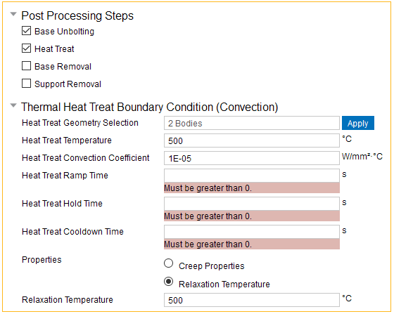
| Post Processing Steps: Heat Treat
| Choose Heat Treat to simulate a heat treatment process, such as annealing, to
relieve residual stresses. In an annealing process, metal is heated in a furnace to a
particular high temperature, held there for a long time (hours or days), and then
allowed to cool slowly.
Choose one of the following properties as the mechanism to account for the stress relaxation:
Affects these tree objects: AM Process Sequence worksheet, Analysis Settings, and Imported Load under Static Structural system. Adds a Transient Thermal system with all its child objects. Note: We strongly recommend you also choose the Base Unbolting option if you choose Heat Treatment. Unbolting the base prior to heat treatment can be especially important to prevent any artificial stress in the base due to fixed boundary conditions and thermal expansion during heating. |
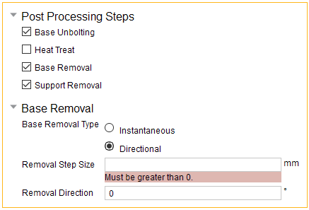
| Post Processing Steps: Base Removal
| Choose Base Removal to simulate the removal of the build from the base.
Base Removal Type determines how the base is removed from the analysis at the end of cooldown:
Affects these tree objects: AM Process Sequence worksheet and Analysis Settings under Static Structural system |
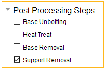
| Post Processing Steps: Support Removal
| Choose Support Removal to simulate the instantaneous removal of the supports from
the part bodies. In the case of multiple supports, removal will be in the order that
the supports were added. Affects these tree objects: AM Process Sequence worksheet and Analysis Settings under Static Structural system |
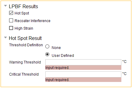
| LPBF Results: Hotspot
| Choose Hotspot to add an LPBF Hotspot result
item to your project so that the appropriate data is written out during solution.
Available only for simulations with thermal solves (LPBF Thermal-Structural
simulation). The Hotspot result tool is used to identify areas of overheating that may
result in problematic thermal conditions. Threshold Definition: Either None or User Defined:
Important: The data is based on the temperature that the build cools down to at the end of each layer right before the next layer is added. It does not represent the "final state" of temperatures at the end of the cooldown step. For more information about interpreting results after the simulation is solved, see Review Results. Affects these tree objects: LPBF Hotspot result item |
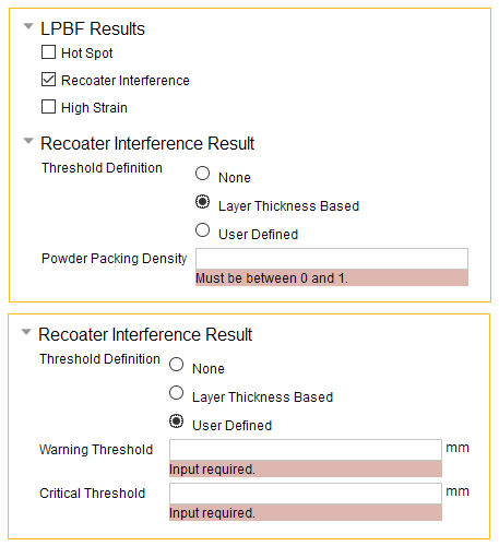
| LPBF Results: Recoater
Interference
| Choose Recoater Interference to add an LPBF
Recoater Interference result item to your project so that the appropriate data is
written out during solution. The Recoater Interference result specifies the level of
Z-deformation at which the build may interfere with the recoater's
spreading. Threshold Definition: Either None, Layer Thickness Based, or User Defined:
Important: The data is based on the Z deformation of each layer right before the next layer is added. It does not represent the "final state" of deformation at the end of the cooldown step. For more information about interpreting results after the simulation is solved, see Review Results. Affects these tree objects: LPBF Recoater Interference result item |
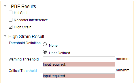
| LPBF Results: High
Strain
| Choose High Strain to add an LPBF High Strain
result item to your project so that the appropriate data is written out during
solution. The High Strain result shows the maximum equivalent strain experienced
during the build process. It can help to identify regions at risk of
cracking. Threshold Definition: Either None or User Defined:
For more information about interpreting results after the simulation is solved, see Review Results. Affects these tree objects: LPBF High Strain result item |