


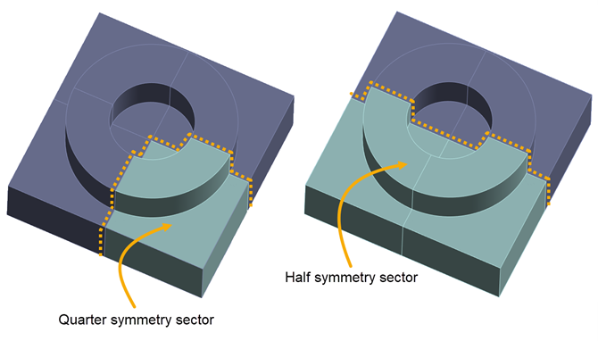
If your model has symmetrical geometry—specifically, if it is symmetric with respect to the part, supports, and build plate, and it has symmetric loading and boundary conditions—you can simulate a sector of a large model to achieve a faster simulation time with fewer resources. Both the base plate and the build (part and supports) should be included in the symmetry sector.
The procedure is the same as described in Symmetry, with a few modifications for the AM process simulation. Specifically, you will need to do the following:
Prepare your part, supports, and baseplate geometries to form a symmetric sector.
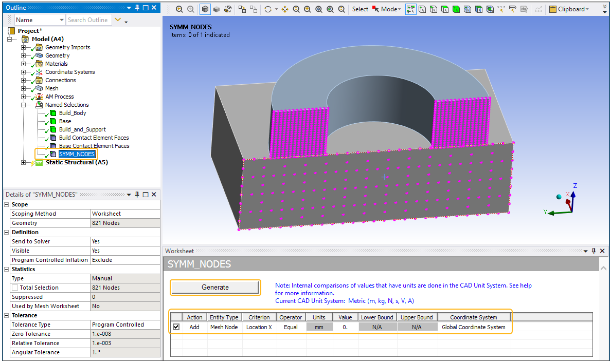
After meshing, create a SYMM_NODES named selection consisting of nodes along the symmetry plane. This named selection is used internally and allows the program to handle the AM boundary conditions properly.
As a structural boundary condition, apply a constraint at the symmetry plane of the build and the base plate. Depending on the mesh type used, this is done in one of two ways:
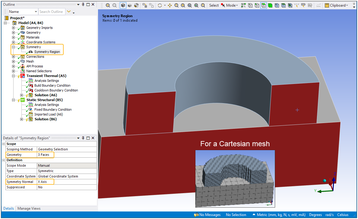
For a Cartesian mesh, where the mesh is associated back to the geometry entities, insert a symmetry region on the geometry faces defining the symmetry planes.
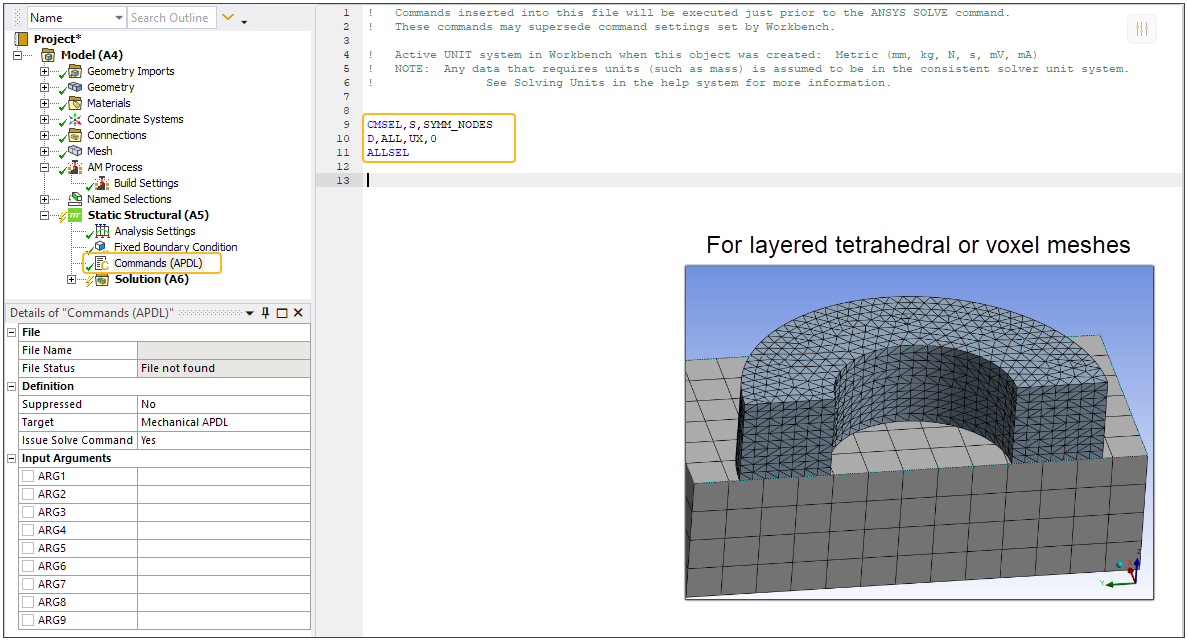
For a layered tetrahedral or voxel mesh, where the mesh is not associated back to the geometry faces, define Mechanical APDL commands that constrain nodes from moving normal to the symmetry planes.
Finally, if your simulation includes a thermal solution, input a Dwell Time Multiple in Build Settings to account for the reduced simulation time that comes with a symmetry model.
For step A, prepare your model in a CAD package, as normal. Procedures for steps B through D are described next.
Procedural Steps
B. Create a SYMM_NODES named selection consisting of nodes along the symmetry plane
Right-click Model in the project tree, and select Insert > Named Selection. Right-click the newly created Selection object (under Named Selections) and Rename it to SYMM_NODES. In the Details view change Scoping Method to Worksheet. In the Worksheet, set up filtering criteria to identify the nodes of interest. In the half symmetry model below, we selected all the nodes along a plane of X = 0. Click Generate to create the named selection of nodes.
C. Apply a constraint at the symmetry plane
For a Cartesian mesh, insert a symmetry region on the faces defining the symmetry plane of the build and the base plate. This will apply a frictionless support boundary condition on those faces. With this boundary condition, no portion of the body can move, rotate, or deform normal to the faces. (The use of a frictionless support is not unique to additive manufacturing simulations.)
Switch to face mode of selection and use Ctrl-left-click to select the multiple geometry faces along the symmetry plane. Highlight Model, right-click and Insert > Symmetry. Right-click the Symmetry object and select Insert > Symmetry Region. In the Details view, be sure that the Symmetry Normal property is set to the axis of the Global Coordinate System that is normal to the symmetry plane, in our example, the X-Axis.
For a layered tetrahedral or voxel mesh, since the mesh is not associated back to geometry faces, planes of symmetry selected in the UI are not recognized. For these types of meshes, you must define Mechanical APDL commands that constrain nodes in the symmetry planes. (Note that a voxel mesh associates back to body entities only, not faces, edges, or vertexes.)
Right-click Static Structural and select Insert > Commands. On the Commands object that appears in the tree, enter the appropriate commands that select the SYMM_NODES nodes, applies a constraint (D command) to prevent motion normal to the symmetry plane, and selects all nodes again. In our half symmetry example:
CMSEL,S,SYMM_NODES
D,ALL,UX,0
ALLSEL
D. For thermal simulations, input a Dwell Time Multiple equal to the number of symmetry sector repeats
For analyses with thermal solutions, such as an AM LPBF Thermal-Structural simulation, this step is required to reconcile the reduced time to simulate the build. For example, the build time for a half symmetry model is ½ of the build time of the full model, so the Dwell Time Multiple should be 2. Similarly, use a Dwell Time Multiple of 4 for a quarter symmetry model, and so on.
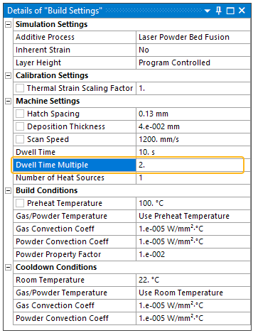
In the project tree, click AM Process > Build Settings and in the Details view under Machine Settings, change Dwell Time Multiple to 2, or 4, or the appropriate number of repeats. In the half symmetry model in our example, we changed Dwell Time Multiple to 2.
The remaining steps are the same as usual for additive simulations.