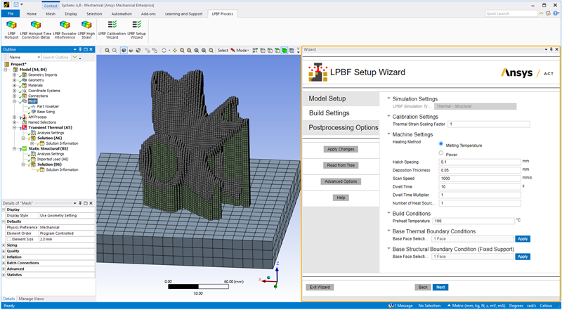
In the Build Settings step:
Simulation assumptions are set by default based on your chosen AM LPBF system.
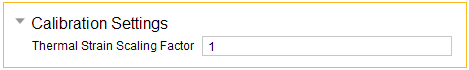
Enter calibration factor(s) as determined from calibration experiments. Use default calibration factors if your goal is simply to examine trends, that is, the effects of variable changes on stress or distortion relative to each other.
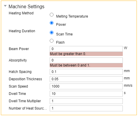
Enter machine settings, which are process parameters that directly influence how the process deposits material. These include Deposition Thickness, Hatch Spacing, Scan Speed, and a number of other factors.
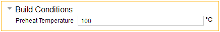
Enter build and cooldown conditions, which are settings pertaining to the environment around the part during the deposition process and during cooldown. These include Preheat Temperature and gas and powder boundary conditions.
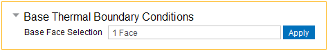
Enter boundary conditions applied on the specified surface of the base, usually the underside surface, during the build and during cooldown. The wizard automatically selects the underside surface of the base by default.
Action buttons are described in the following table.
| Action Button | Function | Action Button | Function |
|---|---|---|---|
Apply Changes
 | Click to apply the actions for this wizard step, which updates the project tree. If you make changes, click Apply Changes again. | Help | Click to bring up help for this wizard step. |
Read from Tree | Click to read the status of objects in the project tree and update the wizard input fields accordingly. Think of this as the opposite action of Apply Changes, which updates the objects in the project tree with inputs from the wizard. | Next | Click to move to the next wizard step. All required inputs on this step must be
filled in to be able to move to the next step. If the button does not appear blue, not
all required inputs are filled in. No actions are performed when you click Next. At times, you may want to fill out all the wizard inputs completely before applying any actions. Clicking Next without first clicking Apply Changes allows you to do that. |
Advanced Options | Click to toggle on/off options related to gas and powder convection. | Back | Click to go back to the previous wizard step. |
Exit Wizard | Click to exit the wizard. Any actions you have performed using Apply Changes will be maintained in the project tree. No additional actions will be performed upon exit. |
Input fields are described in the following table.
| Input Fields | Description |
| Calibration Settings
| Enter Thermal Strain Scaling Factor. This is an optional input that scales the
thermal strains in the structural portion of a Thermal-Structural simulation by a
given value. It is usually determined from calibration
experiments to account for differences in materials, machines, and other
factors. Affects these tree objects: Build Settings |
| Machine Settings
| Enter the Machine Settings, which are settings and process parameters that
directly influence how the process deposits material.
Affects these tree objects: Build Settings |
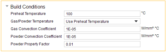
| Build Conditions
| Enter Build Conditions, which are settings pertaining to the environment around
the part during the deposition process. In LPBF, heat loss to the powder is simulated
as a convection boundary condition unless it is explicitly modeled as a body (see
Advanced Options in the Model Setup
step). By default, these conditions will be added as thermal boundary conditions with the default values for temperature and convection coefficients set by the wizard. Convection coefficients default to 10 W/(m)2(°C). Use Advanced Options to customize build conditions.
Affects these tree objects: Build Settings |
| Base Thermal Boundary Conditions
| Select the face of the base where preheat temperature should be applied, usually
the underside of the base. Then click Apply. Use Ctrl-click to select multiple faces.
By default, the underside surface of the base is already
selected. Affects these tree objects: Thermal boundary conditions and loads under Transient Thermal system |
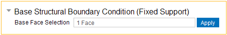
| Base Structural Boundary Conditions
| Select the face of the base where the fixed support should be applied, usually
the underside of the base. Then click Apply. Use Ctrl-click to select multiple faces.
By default, the underside surface of the base is already
selected. Affects these tree objects: Fixed boundary condition under Static Structural system |
| Advanced Options | |
| Build Conditions
| Enter details about the Build Conditions, which are settings pertaining to the
environment around the part during the deposition process. In LPBF, heat loss to the
powder is simulated as a convection boundary condition unless it is explicitly modeled as a body. Convection coefficients default to 10 W/(m)2(°C).
Affects these tree objects: Thermal boundary conditions and loads under Transient Thermal system |
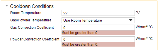
| Cooldown Conditions
| Enter details about Cooldown Conditions, which are settings pertaining to the
environment in the build chamber around the part in the cooldown step after the build
is completed.
Affects these tree objects: Thermal boundary conditions and loads under Transient Thermal system |
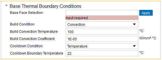
| Base Thermal Boundary Conditions
| Enter details about the thermal boundary conditions applied on the specified
surface of the base, usually the underside surface, during the build and during
cooldown. Boundary condition options include temperature, convection, or an adiabatic
condition (no heat transfer).
Affects these tree objects: Thermal boundary conditions and loads under Transient Thermal system |