


Go directly to procedural steps.
Supports may be imported with your geometry, you may import them as a separate .stl file, or you may generate them directly as elements in Mechanical, or some combination of the three.
Predefined Supports are support bodies that are imported with your part geometry and you will need to identify them as such.
STL Supports are supports imported as .stl files or transferred in automatically from Additive Prep using the transfer to Workbench feature. STL Supports are generally volumeless (that is, not watertight), thin-walled structures created with Additive Prep or other support-creation tools. The thin, intricate support walls that may include perforations are made of many small facets. We use a voxelizing technique, similar to that used in Additive Print, to account for this. The mesh is generated with cubic elements that are internally divided into subdivisions for sampling the presence of material to determine the overall densities of the elements. These, in turn, are used for the material knockdown factors.
STL Support files must be in millimeters. Furthermore, with STL Supports, element size is set by the mesh criteria used for the part. It is for this reason that you must mesh the part before, or at the same time as, meshing the STL Support. If you used a Cartesian mesh, the element size uses the value you specified for Build Element Size. (Element size may be slightly smaller than the Build Element Size in certain cases.) If you used a layered tetrahedrons mesh for the part, the element size will be the value you specified for Layer Height.
Generated Supports are available only for parts meshed with Cartesian mesh (with voxelization option equal to yes or no). These supports generated by the Mechanical application are either automatically detected or user-defined. For automatic detection you specify an overhang angle (the default value is 45° to the horizontal X-Y plane) under which supports will be created. For user-defined supports you select individual element faces under which supports will be created. Supports are generated as elements vertically straight down from the overhanging portion of the build to the base, or to a lower portion of the model if it is in the way.
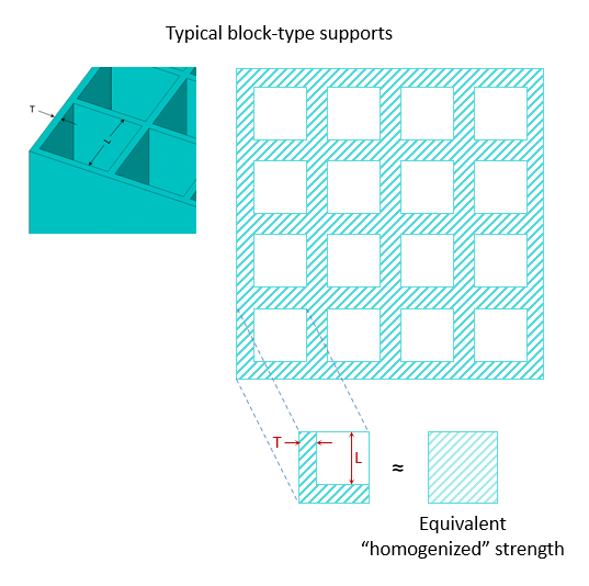
We Treat Supports as Homogenized Solids
In additive machines, supports are printed with the same material as the part but as thin walled structures with less mass than the part. In the simulation we model the supports as an equivalent "homogenized" solid rather than as thin-walled structures. Regardless of whether the supports are predefined bodies, automatically generated, or imported as .stl files, their properties will be scaled down to account for this homogenization technique. Affected properties are elastic modulus, shear modulus, yield strength, density, and thermal conductivity.
Scaling down properties is done automatically for STL Supports. For Predefined Supports and Generated Supports, you will do this in one of three ways:
Specifying an overall multiplication factor. This factor is the ratio of the actual support area to the area of the solid area. For example an overall multiplier of 0.33 will adjust the properties of the supports to be a third of that of the part material.
Specifying individual multiplication factors for each orthotropic direction of each material property.
Specifying wall thickness (T) and spacing (L) for block-type supports, commonly output from support generation tools. In this method, we calculate the equivalent homogenization factor for you.
Procedural Steps
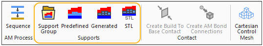
Supports are identified and/or added using the Support Group in the AM Process context menu. As you add supports, objects are added to the project tree under AM Process. You may want to rename these objects to meaningful names if you have many support groups. If things get confusing as you add supports, useful tools are the Hide Support and Hide All Other Bodies options, accessible by right-clicking on any support object.
Predefined Supports
If support bodies were included in the CAD geometry, you need to identify them as supports so that the Mechanical application is aware of which bodies to adjust properties for, or to remove if support removal steps are specified. To identify these predefined supports:
Highlight the AM Process object, and then select the Predefined Support option on the AM Process context toolbar. Or right-click in the Geometry window and select Insert > Predefined Support.
Select the support bodies (geometry selection) with the mouse, holding the Ctrl key down to select multiple bodies (or click, hold, and drag). Click Apply. Or, choose Named Selections.
To scale down material properties, in Details under Support Material Settings, choose Block or User Defined for Support Type. If choosing Block supports, specify Wall Thickness (T) and Wall Spacing (L). If you choose User-Defined for Support Type, you may adjust the material properties by specifying either one overall multiplier or property-by-property multipliers. These multipliers are the ratio of geometric areas of the supports to the areas of the solid geometry, where the areas are the projected areas in the X, Y, and Z directions.
Generated Supports
The Mechanical application's ability to automatically generate supports is available only if the part is meshed with a Cartesian mesh (with voxelization option equal to yes or no). When generating supports, the application can automatically determine their locations or you can specify the support locations.
For automatic detection of generated supports:
Highlight the AM Process object, and then select the Generated Support option on the context toolbar. Or right-click in the Geometry window and select Insert > Generated Support.
Click the Support Group object above Generated Support and change the overhang angle, Hang Angle, to an angle between 0 and 90°, or leave it at the default of 45°.
Right-click Support Group and select Detect and Generate Supports. Supports are generated for all bodies that are part of the build. Note that an option exists to Detect Supports only (that is, not generate supports). This is quite useful if you want to see the effect of changing Overhang Angle. If you are satisfied with the location of supports, then select Generate Support Bodies. Another option allows you to detect and generate supports above a particular Z location (Detect above Z location, in Details of Support Group), allowing further control of where supports are generated.
For user-defined generated supports, you restrict the regions under which supports will be generated by selecting specific element faces in Scoping Method:
Highlight the AM Process object, and then select the Generated Support option on the context toolbar. Or right-click in the Geometry window and select Insert > Generated Support.
Switch to element face mode of selection
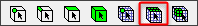 , and use Ctrl-left-click to select
multiple element faces, or double-click-left to select all the elements on a surface. Click
Apply in the Details panel.
, and use Ctrl-left-click to select
multiple element faces, or double-click-left to select all the elements on a surface. Click
Apply in the Details panel. Right-click Generated Support and click Generate Support Bodies.
Important: Supports are generated as elements only (that is, there are no
corresponding geometric bodies created for the new supports). When viewing geometry in the
Geometry window you won’t see the supports. You will see the support elements when you
select the AM Process object (or one of its children), or the Mesh object. Or you can use the
Show Mesh toggle button  to reveal the
mesh even when the Model object is active.
to reveal the
mesh even when the Model object is active.
More importantly, if you would like to use the supports generated in Mechanical in your final print strategy, you will need to convert the elements to geometric bodies for the .stl file required by the printer.
STL Supports
The workflow is slightly different depending on how you add STL Supports. They can be transferred in automatically from Additive Prep or imported from an STL file. Both methods are described in step 1 below.
To mesh STL Supports transferred in automatically from Additive Prep:
When supports are transferred automatically from Additive Prep, they are not scoped to any particular body. That is, they are not associated to the part body. In the project tree, click to expand the Imported Supports object and then click the STL Support object. In the Geometry window, select the body representing the part and click Apply for the Geometry in the Details view of STL Support.
To import and mesh STL Supports from a file:
Before inserting the STL Support, be sure the part is meshed and the build geometry is identified in the AM Process object. Highlight the AM Process object, and then select the STL Support option on the context toolbar. Or right-click in the Geometry window and select Insert > STL Support.
In the Details view of STL Support, identify the source of the .stl file, either a file (default) or a previously imported STL Construction Object. Click File Name to navigate to the appropriate folder and select your .stl support file.
In the Details view of STL Support, change the Length Units, as needed. The default is millimeters. Most often, this is what you want.
Identify the STL Support Type by selecting Volumeless or Solid from the drop-down. Volumeless (default) is for non-watertight supports such as block, heartcell, rod, or line supports created by Additive Prep. Most often, this is what you want. Choose Solid for solid bodies that are watertight, such as custom supports created in Additive Prep.
For Volumeless support type, adjust the Wall Thickness, as needed, according to the single-bead thickness set by your machine.
Adjust the Subsample Rate, as needed. For most cases, we recommend using the default value of 5.
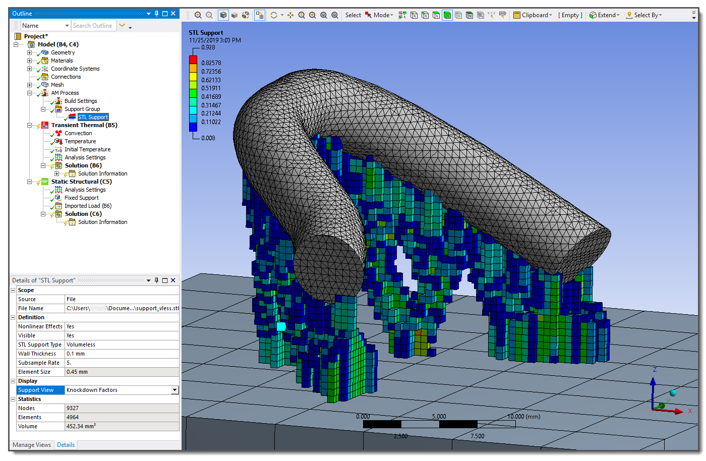
The following figure shows a curved bar model with tree supports generated in Additive Prep imported as an STL Support file.
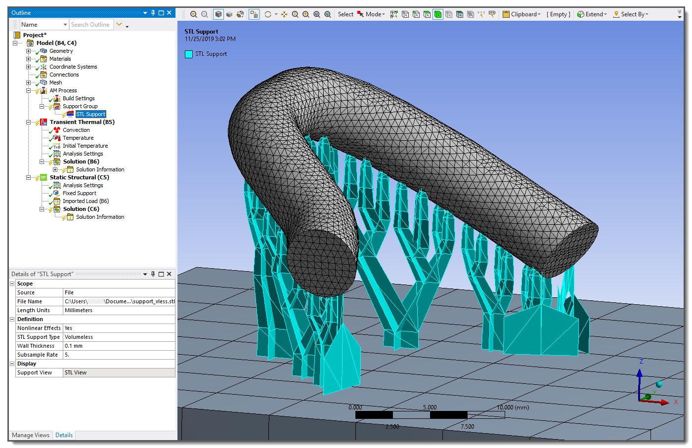
The support structure will be meshed with cubic elements. Each cubic element is divided into sampling regions to determine density of support material within that element. These are used as material property knockdown factors. A Subsample Rate of 5 (default) = 5 x 5 x 5 = 125 subdivisions. Subsample Rate affects the accuracy of element density.
Right-click the STL Support object and select Generate Mesh to mesh the support.
Use the Support View (under Display) to switch back and forth among the view options of STL View, Mesh View, or Knockdown Factors. (Or, the knockdown factors may be turned on using Display Style in the Mesh object Details view.)
Hint: Look for the tiny icon to the left of an object in the project tree for a clue about its status. For example, if you see a question mark next to an STL Support object, it means you have not scoped it to a part yet (if supports were transferred from Additive Prep) or identified a file name yet (if supports were inserted via an STL file). If you see a yellow lightening bolt, it means you have not generated the mesh for it yet. You will see a green check-mark once you have performed all relevant tasks.