There are several Design for Additive Manufacturing (DfAM) considerations to be aware of that affect the cost and quality of your part. Variables include:
Part design (thicknesses, overhangs, edges, holes, desired surface finish)
Orientation on the base plate (affects time to print, number of support structures, and number of replicate parts that can be nested on a base plate)
Support structures (serve to stabilize part, lower deformations, conduct heat away from part, but more supports increases print and finishing time and cost)
In particular for support structures, you should think ahead about how you will remove them. In some cases you may even need to design tooling rails onto the part in order to be able to hold the part while supports are removed.
Location of Supports
In SpaceClaim, under the Facets tab, use the Overhangs tool to detect where supports will be generated. This is a very useful tool to determine, in advance, overhang locations that may need supports.
Cleanup of Facets
If you have an .stl file, be sure to clean it up to eliminate gaps and slivers before importing it into Ansys Workbench.
Under Facets, the Check Facets and the Auto Fix tools are quick ways to find and fix problems in faceted bodies.
Use Facets > Thickness to identify thin-walled features.
To Share Topology or Not?
The requirement that geometric bodies be meshed in uniform layers in the Z direction is unique to additive manufacturing simulations. These uniform mesh layers must be conformal even for multi-body parts or geometries consisting of separate part and support bodies. That is, not only must faces, edges and vertices among different bodies to be 3D printed be aware of each other in order to share information in the simulation, they must also be sliced into layers sharing the same step sizes in the Z direction. Together, the part and the supports constitute "the build."
Two methods in the Mechanical application are available to achieve these uniform mesh layers, one using a Cartesian (brick) mesh and one using a Layered Tetrahedrons mesh. Whether you share topology between bodies in the build—or not—upstream in the CAD program depends on which of these mesh methods you will use.
Use the following criteria for deciding which type of mesh method to use:
Use a Layered Tetrahedrons mesh if:
Your geometry has thin walled features, organic curves, and/or holes.
Use a Cartesian mesh if:
Your geometry is blocky or chunky without fine features or holes.
You know you will be using AM octree adaptive meshing to coarsen the mesh for reduced simulation time. (The AM Octree method is not supported with the layered Tetrahedron mesh method.)
You know you will be generating supports in Ansys Mechanical. (Auto-generated supports are not supported with the layered Tetrahedron mesh method.)
Once you've decided which type of mesh method to use, use one of the following approaches, as appropriate.
If using a Layered Tetrahedrons mesh:
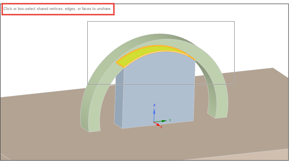
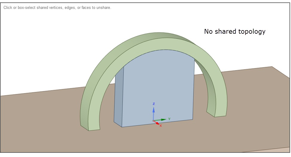
Do not share topology in the CAD program. To do this in SpaceClaim, under the Workbench tab, use the Unshare tool to unshare coincident topology.
Or use Explode Part in DesignModeler.
If using a Cartesian mesh:
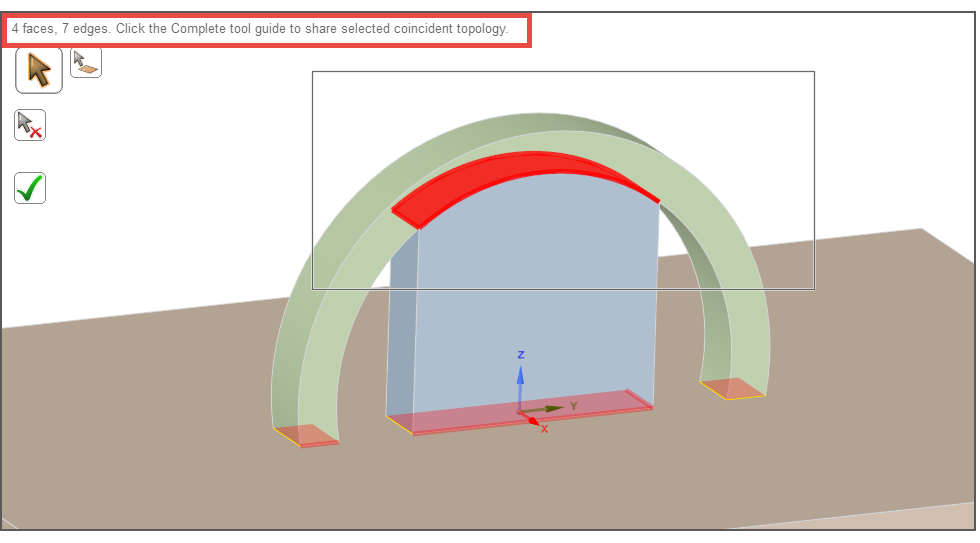
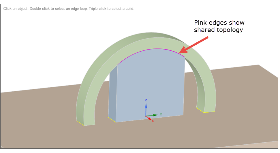
Select all bodies that are associated with the part and the supports and share coincident topology. To do this in SpaceClaim, under the Workbench tab, use the Share tool to share coincident topology. For a step-by-step guide, see the video tutorial, Share Topology.