


Introduction
The Substructure Generation analysis uses the component mode synthesis (CMS) to:
Condense all the finite elements of your model into one “superelement” that is represented as a matrix.
Create load vectors from the loading conditions and constraints that you apply. In addition, you can use an upstream Static Structural analysis to create pre-stress effects in the Substructure Generation analysis solution.
Once you have solved the analysis, you export this generated data as an Exported Condensed Part (.cpa) file for use in another appropriate simulation .
Note: The load vectors extracted from the imported condensed part (.cpa) file are applied as loads in the use pass of the MSUP Harmonic Response analysis. No other analysis consumes these load vectors
Benefits
Substructuring reduces computer time and enables the solution of very large problems with limited computer resources. In a nonlinear analysis, you can substructure the linear portion of the model so that the element matrices for that portion do not need to be recalculated at every equilibrium iteration. In a structure with repeated patterns (such as the four legs of a table), you can generate one substructure to represent the pattern and simply make copies of it at different locations, thereby saving a significant amount of computer time.
Limitations
Note the following limitations for this analysis:
This analysis type is supported for the Mechanical APDL solver only.
This analysis does not support beam End Release, Constraint Equation, or Coupling objects.
This analysis does not support imported loads or imported connections from external mesh files except for Imported Pressure, Imported Constraint Equations or Coupling, and Imported Body Temperature (when Beta Options are active).
The Master Degrees of Freedom Nodes (MDOFs) specified in the Mechanical application may be reduced by the solver during the solution of the analysis. This could be the result of a constraint defined on the MDOF nodes. The application reports this with a warning. For this case, there could be a discrepancy between Mechanical selected MDOFs and solver computed MDOFs as it might have been reduced due to over constraint. This is not recommended, and you should review the model before proceeding with use pass. A warning message will also display while eliminating the redundant degrees of freedom.
The contact setting is not supported for the Formulation property.
The only supported Joint types are Fixed and Bushing (with the property set to ).
Most element types can be used to generate a substructure. In general, the only restriction is that elements within the superelement are assumed to be linear and cannot use Lagrange multipliers. See the Generation Pass section of the Mechanical APDL Substructuring Analysis Guide for additional information.
Points to Remember
All active bodies in the model will be condensed into one substructure (superelement).
The substructure analysis can be linked to upstream Static Structure analysis in order to consider the prestressed effects of the structure. However, when you specify a pre-stress analysis, the Substructure Generation analysis only supports the following loading conditions:
This analysis supports Imported Pressure, including both real and imaginary values.
Preparing the Analysis
As needed throughout the analysis, refer to the Steps for Using the Application section for an overview the general analysis workflow.
Establish Analysis Settings
The analysis includes the following Analysis Settings categories:
Note: The maximum value for the Number of Load Vectors property is limited by the memory available on your computer.
Solver Controls: Direct is the only supported Solver Type property option.
Define Pre-Stress
If your analysis includes an upstream Static Structural system, specify the properties of the Pre-Stress (Static Structural) object. The analysis considers the pre-stressed inertial loads and boundary conditions during the generation pass. This is a result of the Load Control property of the Pre-Stress object being set (by default) to the . See the description of the Load Control property in the Pre-Stress object reference for more information.
Specify Interfaces
You specify interfaces on the Substructure Definition object using Named Selections and Remote Points.
Tip: To automatically create a Named Selection and a corresponding interface (in the Worksheet):
Select the object.
From the window, select a supported geometric or mesh entity on the model.
Right-click and select .
Define Substructure Definition Object
Specify the properties for the Substructure Definition object, including:
| Category | Properties/Options/Descriptions |
|---|---|
|
Geometry |
Geometry: Read-only property that displays the number of bodies of the model. |
|
Definition |
Physics Type: Read-only property indicating the physics type (Structural). Matrix Reduction Method: Indicates the currently supported matrix reduction method - Component Mode Synthesis. Interface Method: Options include (default) or . Lumped Mass Formulation: Specify the desired lumped mass matrix formulation. Options include (default), , and . The setting uses the element-dependent default mass matrix formulation and the setting uses a lumped mass approximation. Generate Damping Matrix: Specify whether to generate a damping matrix. Options include (default), , and . |
|
Interfaces |
Number of Interfaces: Read-only display of the number of interface entries detected by the application. Number of Master Nodes: Read-only display of the number of superelement master nodes resulting from interfaces. |
Note: The application treats added masses (from Point Masses and Distributed Masses) as internal to the superelement.
Apply Boundary Conditions
Without considering the Limitations, the analysis supports the following boundary conditions:
- Imported Connections
Imported Constraint Equations or Coupling
Note: This analysis does not support native Constraint Equation or Coupling objects.
- Inertial
- Loads
- Supports
The following Supports can be used in this analysis:
Fixed Support
Displacement
Remote Displacement
Frictionless Support
Compression Only Support
Cylindrical Support
Elastics Support
- Direct FE (node-based Named Selection scoping and constant loading only)
- Imported Loads
Note: The application computes load vectors for each defined load. Once you export the solution (see below), you use these load vectors in another analysis through the Imported Condensed Parts object. Load vector information displays in the Worksheet when you select the Imported Condensed Parts object.
Specify Results
The only result supported by this analysis is Total Deformation.
Perform Solution
The Solution Information object presents continuous updates of any output from the solver and provides valuable information on the behavior of the structure during the analysis.
Select the Solution object to view the frequencies obtained from the solution process in the Graph and Tabular Data windows.
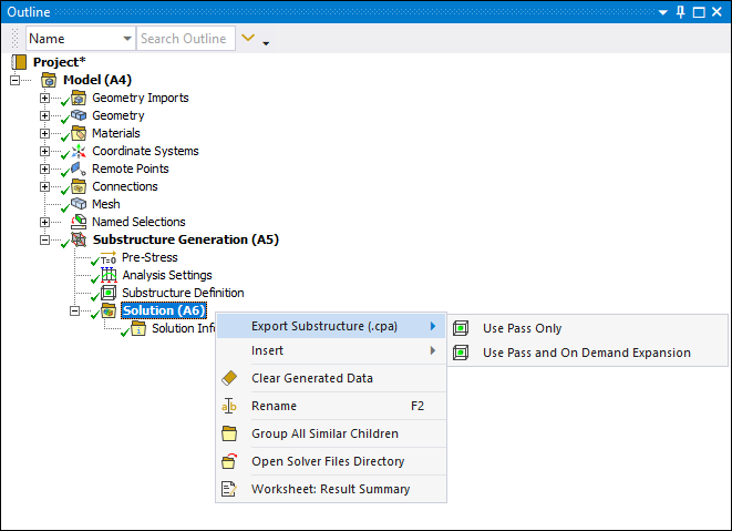
Exporting Substructure Solution
Once you have solved your analysis, you can export the generated superelement for use in a different session of the application. Right-click the Solution object, select , and then select one of the following options:
: Using this option, the application generates solution files required to perform a Use Pass analysis. No Expansion Pass can be performed when this option is selected.
: Using this option, the application generates solution files required to perform a Use Pass analysis as well as On Demand Expansion.
A progress bar displays during the export operation and offers an option to stop (red square icon) the process.
Note: If you set the Future Analysis property (Analysis Settings>Analysis Data Management) to , the application automatically includes the additional files necessary to perform a downstream Rigid Dynamics analysis in the exported file.
References
For a more detailed look at this analysis type, see the:
Substructure Analysis section of the Mechanical User's Guide.
Mechanical APDL Substructuring Analysis Guide