When pressures are transferred to a structural or harmonic analysis, an Imported Pressure object can be inserted to represent the transfer. For more procedural steps for applicable transfers, see the Imported Boundary Conditions section. Be sure to review the Additional Mapping Options outlined below.
Pressure Application Options
The Imported Pressure load provides the following properties that enable you to define how to map and apply the load:
Shared Reference Body: This property is a scoping feature used to apply the Imported Pressure to shared faces or edges between two bodies. When you have properly scoped the geometric entities, using either Geometry Selection or an appropriate Named Selection, the property provides a drop-down list of the names of the bodies that share the scoped features. By selecting a body from this list, you are specifying that the pressure be applied to its surface or edge. Once selected, the Geometry or Named Selection property displays a parenthetical of the shared face or edge, such as “(1 Shared Face/1 Shared Edge)” to indicate the condition.
Note:When working with the shared edges of a 2D model, the Applied By property must be set to .
Edges can be shared between a surface and line body, but the line body cannot be specified as the Shared Reference Body or the property becomes invalid.
Apply To: This property that enables you to map and apply the load to either the centroids of the (default) or to the of the elements included in the scoping. Also see the Additional Mapping Options topic below.
Applied By: You use this property to specify the imported load as either (default) or . The option applies the pressure using the surface effect elements created on the top of the scoped geometry. The option applies the pressure directly onto the faces (3D) or edges (2D) of the solid/shell elements.
Apply To Initial Mesh: If you have a Nonlinear Adaptive Region object present in a Static Structural analysis, this property is displayed. You use this property to specify whether the boundary condition is applied directly to the initial mesh or to the newly generated mesh. The setting for this property is not supported when the Applied By property is set to . For more information, see the Initial-Mesh Loading and Constraint section of the Mechanical APDL Nonlinear Adaptivity Analysis Guide.
For Substructure Generation analyses, the Details pane displays the Load Vector Controls category. This category includes the following properties.
Load Vector Assignment: Options include (default) and . If you select , a Load Vector Number property displays, as described below, enabling you to define the value.
Load Vector Number (Real): Use this property to manually specify a Load Vector Number (Real) value. This value can be any number greater than 1 – the application reserves this value for pre-stressed Substructure Generation analyses. If multiple loads have the same load vector number, the application groups these loads during the solution process.
Load Vector Number (Imaginary): This property is only visible if the imported data includes imaginary values. This value can be any number greater than 1 – the application reserves this value for pre-stressed Substructure Generation analyses. If multiple loads have the same load vector number, the application groups these loads during the solution process to generate a single load vector that is the combined effect of all grouped loads.
Note:
For large-deflection analyses, this load is applied to the original loaded area by default, not the new area. When the Applied By property is set to:
For surface bodies, the thickness of each target node is ignored when data is mapped. When importing data from an External Data system, the Shell Thickness Factor property enables you to account for the thickness at each target node, and consequently modify the location used for each target node during the mapping process. For additional information, see External Data.
If you scope two Pressure objects to the same geometry, and specify the loads in the same direction, using the option, the pressures do not produce a cumulative loading effect. The Imported Pressure object that you specified last takes priority and is applied, and as a result, the application ignores the other Imported Pressure object.
An Imported Pressure applied using the option and a Imported Pressure applied with the option produce a resultant effect.
If your analysis includes some combination of a Imported Pressure, Pressure, a Force, and a Hydrostatic Pressure load, and 1) all are set to the Direct option and 2) share the same scoping, 3) have the same Direction, whichever load was written to the input file last, overwrites all previous loads.
This imported loading condition supports the Vector Display options.
Important: Note the following limitations when using the option for Applied By property and when the Define By property is set to :
Only supported when the target solver type is Mechanical APDL.
Not supported for vertices and edges of Solid bodies and Line Bodies.
Not supported on bodies associated with General Axisymmetric and Condensed parts.
Not supported if the model has any crack defined under the fracture folder.
Not supported if the analysis includes a Nonlinear Adaptive Region object, 1) the Loaded Area property is set to , and 2) the Large Deflection property (Analysis Settings > Solver Controls) set to .
In a multiple step analysis, if you define more than one load (Imported Pressure, Pressure, Force, or Hydrostatic Pressure) using the option and a , and they share the same scoping, deactivation of a particular load step in one of these loads could delete all the other loads in that load step and following steps.
Additional Mapping Options
Imported pressure loads from External Data can be mapped and applied to either the centroids () or of the selected 3D element faces or element edges (2D) using the Applied to property.
When the Applied To property is set to , the Filter property under the Scopecategory enables you to select a subset of the scoped element faces/edges and imports the load only on the specified subset. To filter a subset of element faces/edges, follow the following steps:
Create a nodal Named Selection to select all the nodes in the region of interest.
Select the created named selection in the Filter property. You may also choose any pre-existing nodal Named Selection.
The filtered subset of element edges/faces is then determined by the following:
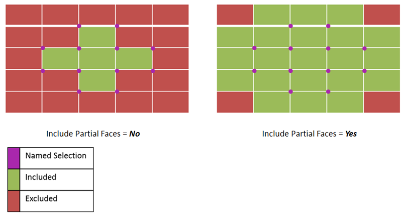
The element faces/edges which have all their corner nodes defined in the filter will be included in the mapping
For the element edges/faces whose corner nodes are only partially defined the filter, that is, the faces/edges which have some corner nodes included in the filter, but not all the Include Partial Faces/Edges property can be used to include or exclude the element faces/edges from the scoping.