This section describes how to use the Imported Condensed Part object. Go to a section topic:
Overview
Using an Imported Condensed Part object, you can import superelements from another system into your current system. This enables you to use the superelements in the current solution ("Use Pass"). Imported Condensed Part objects are defined by the following information:
A set of master nodes that represents the reduced superelement being imported.
A set of interfaces defining the master nodes that are retained when the application generates the superelement.
A list of controls that define the location and node numbering for the imported superelement.
Application
The following steps assume that you have already created a Condensed Geometry object and that you are prepared to import a supported file type.
To specify an Imported Condensed Part object:
Right-click the Condensed Geometry object and select > Imported Condensed Part. You can also select the Imported Condensed Part option from the Condensed Geometry Context tab. Once inserted, the Worksheet automatically displays.
Select the desired file type from the drop-down list of the Import File Format property. Supported file formats include:
(default): You create this file by either exporting Condensed Parts or exporting a Substructure Generation solution.
Using the Condensed Part File property, define the path to the import file.
Right-click the new object and select Import Condensed Part. A progress bar displays during the import operation and offers an option to stop (red square icon) the process. Once imported, the View Transformed Data option/display activates. If you need to make manual Worksheet entries, see the steps provided in the Worksheet Options and Actions topic below.
As needed, modify the following properties:
Unit System
Locating System: Specify a desired Coordinate System to orient the imported super element. The default setting is .
Node Offset: Specify an offset number to be used on the imported nodes. This property has a default setting of Program Controlled that equates to the value zero. Using this setting the application automatically offsets the node number based on the Mesh. Any value that is greater than zero offsets the Node Ids by that value.
Note:
Remote Points need to be connected to the interfaces of the Imported Condensed parts. To avoid rigid body modes, set the Behavior property of the Remote Point to Coupled.
The outline of the Imported Condensed Part is only displayed on the part if the information is available in the selected source file.
Worksheet Options and Actions
There may be times that you need to import or copy and paste data into the Worksheet using the available interface options. The Worksheet presents interface options and interface data based upon file format.
- Exported Condensed Part
For the format, interface data includes ID, Name, Node Connectivity, and Number of Nodes. Only the option is available for this file format.
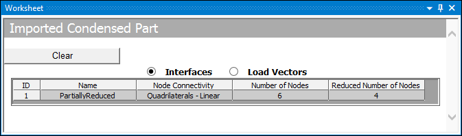
Note: If a Master node of the interface is reduced during the Generation Pass, the Worksheet displays a column listing the Reduced Number of Nodes.
- Generation Pass Output and Super Element Matrix
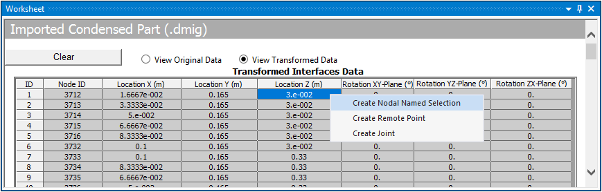
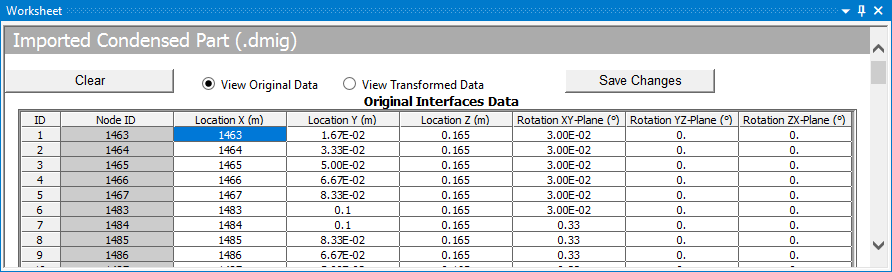
For the and formats, interface data includes Node ID, Location and Rotation data. In addition, the following radio buttons display and enable you to display either the original or transformed state of the interface data.
Important: For the file format, Mechanical reads the file’s matrices in the order shown below. Make sure that the source file uses this order because the application only processes the first three matrices.
1st: Stiffness Matrix 2nd: Mass Matrix 3rd: Damping Matrix Tip: If you have multiple files for each matrix, use the following API method on Project object to generate a single file that uses the required order of matrices.
CombineTextFiles(primaryFilePath, secondaryFilePath)
| Worksheet Option | Description |
|---|---|
|
View Original Data |
Radio button that displays imported data when you use the Read Interface Data option. It displays Original Interface Data. |
|
View Transformed Data |
Radio button that activates automatically once the import process is complete. It displays Transformed Interface Data. |
|
Read Interface Data |
This option is available when the View Original Data option is selected, and no data has been imported. When selected, the application reads file data and populates the table with read-only Node ID and Location data from the selected file. This enables you to validate the file data. If the file contains no location data, the Location fields in the table will contain zeros (0). To complete the import process once you have read a file, right-click the object and select . |
|
Edit |
Select this option to enter data manually. Manual data entry can be done using copy and paste. This includes copying data from a spreadsheet. Properly select all location data from your spreadsheet and highlight the first data cell, Location X, and then paste all data. See the Worksheet Examples topic below for more information about manually entering data. |
|
Save Changes |
Save table data. |
|
Clear |
Clear all table data. |
Worksheet Examples
The following examples describe the scenarios when importing data. Go to a topic:
Overview
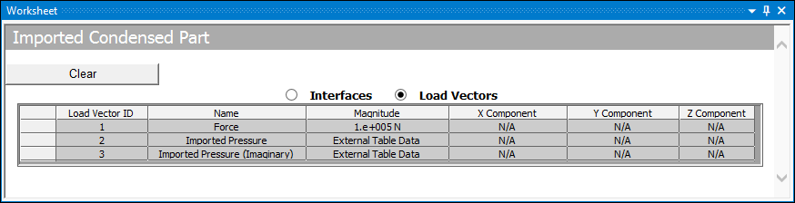
A successful import for an file is shown here. The worksheet for this file type has two display options: Interfaces and Load Vectors, as described below.
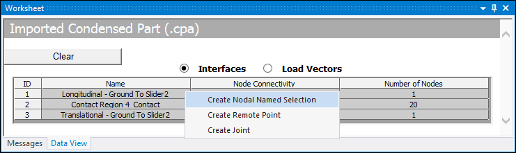
Interfaces
Whether user-defined or system generated, the condensed part interfaces are listed in the worksheet by default. As illustrated, you can right-click the data presented in the Worksheet to create Nodal Named Selections, Remote Points, and Joints for each interface that can then be used to define connections and/or boundary conditions.
Note: If you select the option on the Imported condensed Part:
Created Named Selections or Remote Points will lose their scoping. When you re-import the Imported Condensed Part, the Named Selections or Remote Points get reassociated with their original scoping.
Contact Region scoped to a Named Selection which is created from the Interfaces of the Imported Condensed Part remains properly defined.
During the solution Generation Pass, the application could reduce the Master degree of freedom (MDOF) as a result of an internal constraint equation. This could result in the reduction of the Master node (see M Command). For example, if you have an interface with six nodes and due to an application generated internal constraint equation, the solver ignores two Master nodes. This results in an interface of only four Master nodes. If the application reduces a Master node, the Worksheet displays an additional column, as illustrated below, that shows the exact number of nodes on that interface. This node value is supported by the options to create Nodal Named Selections, Remote Points, and Joints.
Load Vectors
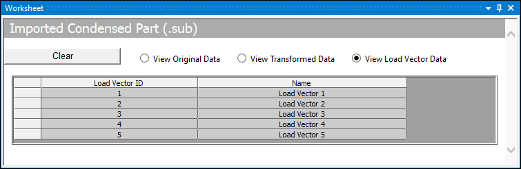
Load Vectors, as well as prestressed load vector values, are exported from a solved Substructure Generation analysis as a .cpa file, and imported and displayed in the worksheet, as shown in the example below. If no load vectors are available, the table is blank.
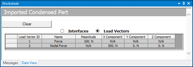
Load vectors are also generated for imported loading conditions.
Load vectors can also be imported from a file that was created in the Mechanical APDL application, as illustrated here.
Note: Depending upon the specified loading, the following analysis types automatically create load vectors during the solution process. If you include an Imported Condensed Parts object in either analysis, all of the load vectors will be contained in the solution output file.
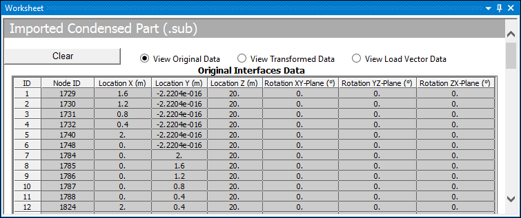
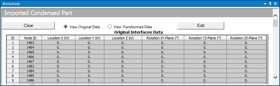
View Original Data
Here is an example of the View Original Data option for the data read from a file.
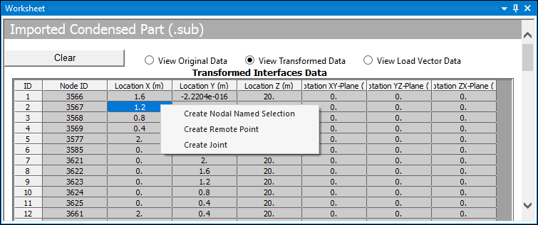
View Transformed Data
Once imported, the View Transformed Data option automatically displays. Here you can see transformed data. Note the Node ID values for this example versus the above example. These values are based on the Actual Node Offset value which for this example is 3261.
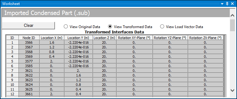
In addition, for the View Transformed Data option, you can create Nodal Named Selections/Remote Points/Joints for each interface.
Manually Importing Spreadsheet Data
For the file format, there may be times that you need to manually copy data into the worksheet table. For the Worksheet example shown here, no location data was found in the file. To make manual entries, select the button.
Properly select all location data (only) from your spreadsheet.
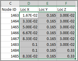
Highlight the Location X field as illustrated below. This ensures that the data will be properly distributed throughout the table when you paste.
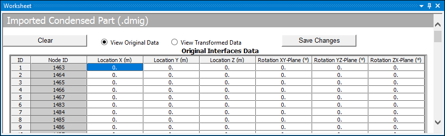
Review the pasted data and then select the button.
Once saved, right-click the object and select . This action imports the data, and automatically displays Transformed Interface Data that you can use to options to create Nodal Named Selections, Remote Points, or Joints for the selected interface.
Note:
When you create a Nodal Named Selections or a Remote Point, the application automatically scopes to the object for the selected interface nodes. For a generated Remote Point, the Behavior property is automatically set to .
When you create a Joint, the application creates a Joint whose Reference Side is automatically scoped to the selected interface nodes with the option specified.