


Remember the following notes when using the Face Meshing controls for mapped meshing:
The blue status icon that may appear in the Tree Outline indicates that a mapped mesh cannot be provided on the scoped topology. One of three scenarios triggers the icon:
The face cannot be map meshed.
The quality of the mapped mesh was not acceptable and a free mesh was generated.
If Constrain Boundary is set to , the mesher will fail if the boundary of a mapped mesh must be modified.
For mixed/solid shell parts, a Face Meshing control cannot be scoped to a sheet face if the face is adjacent to a solid body. In such cases, the meshing of the sheet face will fail.
To assist you in working with mapped face meshing, you may want to use the Show Mappable Faces, , and/or features. The Show Mappable Faces feature selects all mappable faces automatically and highlights them in the Geometry window. By using the feature, you can find out whether bodies are sweepable (before and after modifying vertex types). By using the feature, you can verify that your mesh settings are correct.
When sweeping:
If the sweep method is applied to a body and mapped face meshing is defined for either the body's source or target face, the sweep mesher will fail if a mapped mesh cannot be obtained for the face.
When mapped face meshing is defined for a side face, the mapped mesher will loosen its tolerances on determining whether a face is mappable.
When sweeping and using advanced mapped meshing controls, you must set vertex types for both the source and target faces.
When a face has only 4 vertices and 4 edges, and mapped Face Meshing controls are applied, the only factor that will determine a successful mapped mesh is element quality.
Note: It is often helpful to use the Show Vertices option to ensure edges are complete and do not have unintended segmentation. If an edge is segmented, it could mean that a face you think should be successfully mapped actually has 5 vertices and 5 edges. To help resolve such issues, you can define a virtual edge or use advanced mapped Face Meshing controls.
An effective technique for mapped meshing on surface bodies is to select all faces on the body and let the mesher determine which faces should be map meshed and which faces should be free meshed.
If the mapped Face Meshing controls are attached to faces with exactly two boundary edges or two sets of boundary edges, an additional option, Internal Number of Divisions, is available. This option allows you to specify the number of layers of elements that will be generated between the two boundary edges.
If there is a conflict between Internal Number of Divisions and a Face sizing control, the mapped face control's Internal Number of Divisions value will take priority.
If there is a conflict between Internal Number of Divisions and a parallel Edge sizing control, the Sweep mesh method will respect the Internal Number of Divisions unless the size is hard, in which case it will return an error notifying you of the conflict. The MultiZone mesh method will respect the Edge sizing control.
If there is a conflict between the Internal Number of Divisions and the number of divisions on a Sweep mesh method, the Sweep mesh method will return an error notifying you of the conflict.
See Face Characteristics for Annular faces in the table below for more information.
The table below provides an overview of types of faces and how various mesh methods handle when mapped Face Meshing controls are applied to them.
| Mesh Method | Face Characteristic | |||
|---|---|---|---|---|
|
Circular 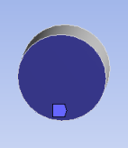 |
Triangle 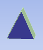 |
Annular  |
Internal Loops 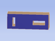 | |
| Not supported. You must free mesh these faces. | Not supported. You must free mesh these faces. As side faces, triangle faces can be mapped to obtain a wedge mesh at one corner, depending on source face selection.  | Supported. In the Details View, the Internal Number of Divisions option is activated so you can specify the number of divisions across the annular region. The option is set to 3 in the example below:  |
Not supported. You must free mesh these faces, but note the following: If there is just one internal loop, it is treated as an annular case. For example, if the model above were split in half, you would have a square annulus which would mesh similar to the circular annulus model. | |
Supported, but mesh quality is poor.  You can use MultiZone or Mapped Mesh to obtain an O-Grid for better quality in corners.  | Supported. Triangle faces are submapped to tri primitives.  As side faces, triangle faces can be mapped to obtain a wedge mesh at one corner, depending on source face selection.  | Supported. In the Details View, the Internal Number of Divisions option is activated so you can specify the number of divisions across the annular region. The option is set to 3 in the example below:  | Ignored for source faces. However, internal loops are supported for side faces. If this example is meshed top to bottom, and has mapped faces defined on the sides, it meshes as follows: 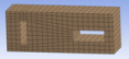 For more information on using mapped Face Meshing with side faces, see Side Face Handling of Imprinted Regions. | |
With fillets, chamfers, or large or small angles
It is not always clear which vertex(es) should be used as the corner(s). Using virtual topology to merge edges or split faces, or using mapped face meshing vertex controls may help.

When there are a large number of segments along a side. This situation may create difficulties in assigning incremental edge assignments that lead to good quality mesh. In these cases, adding a face split is a good way to ensure the interval edge assignment is done correctly.
Concerns over the mappability of faces may be different depending on whether the faces are source/target faces or side faces. For sweeping to be successful (regardless of whether Sweep, Thin Sweep, or MultiZone is used), all side faces (that is, all non-source/target faces) must be mappable. Ensuring side face mappability is most critical to ensure a successful swept mesh. Ensuring a source face can be mapped should be a lower priority, and your strategy for sweeping should account for this difference. You can use the Show>Mappable Faces option to help determine mappability of faces.
In addition to the mappability of each individual side face, the collective set of faces for a given side may present a problem. For example, for a collective set of faces, all parallel edges need to have the same number of divisions from the top to the bottom of the sweep. Ensuring all side faces of a swept body are mappable does not always ensure the body is sweepable. For example, if parallel edges of a mapped face change in direction, a source edge could become a side edge and make the body impossible to sweep. Also, edge splits on one face need to propagate through the collective set of faces while maintaining a reasonable quality mesh. Reducing the number of edge splits may simplify the sweeping and lead to a better quality mesh. This effect is the result of the simplification in the "interval edge assignment," or the requirement for the mesher to have the same number of divisions along the sweep path.
Extending splits through the set of side faces may also help the mesher with the incremental edge assignments, as well as with constraining the grid lines along the sweep path to control the mesh quality. The imprinting that occurs with MultiZone creates further complications. See Side Face Handling of Imprinted Regions for more information.