This section describes the steps for setting basic Face Meshing controls for mapped face meshing.
To set basic Face Meshing controls for mapped meshing:
Insert a mapped face meshing control by highlighting Mesh in the Tree and right-clicking to view the menu. Select .
In the Mapped Face Meshing Details view, underDefinition, Mapped Mesh is set to Yes by default.
Under the , select Method as or . The option is available only for sheet models.
Specify the to provide number of divisions across annular regions or seamless cylinders. (The Internal Number of Divisions option is activated when the Face Meshing control Definition is set to Mapped Mesh and the control is scoped to faces made up of two loops.) The default value is 0.
Select to specify whether you want to allow the mesher to split the boundary of a mapped mesh region to aid in meshing of adjacent faces. You can select Yes (constrain boundary; no splitting is allowed) or (do not constrain boundary; splitting is allowed). The default is . See Notes on Face Meshing Controls for Mapped Meshing for related information.
Right-click the Mesh object in the Tree and click to generate the mesh.
Note: When Mapped Meshing fails on a surface, the mesher automatically meshes the surface using Aggressive Tri Reduction.
To access the Face Meshing,
On the Tree Outline, right-click Mesh and click Insert > Face Meshing.
Or
On The Tree Outline, click Mesh and click Face Meshing in the Mesh Context tab on the Ribbon.
Or
Right-click on the face and select Insert > Face Meshing.
Mapped Face Meshing Details view has the following options:
Scope
Scoping Method: Allows you to scope geometry or named selection. The default value is Geometry Selection. The available options are:
Geometry Selection: Allow you to scope the geometry bodies. When you select Geometry Selection, the Geometry allows you to select the geometry from the Geometry window
Named Selection: Allow you to scope the named selection from the available named selections.
Definition
Suppressed: Allows you to suppress the method control. The default value isNo. When Suppressed is Yes, theActive provides the number of suppressed parts and is read-only.
Mapped Mesh: Generates the structured mesh for the selected geometry faces when set to Yes. When Mapped Mesh is No, maps the faces automatically and generates quad dominant mesh.
Internal Number of Divisions: Allows you to set the number of divisions across annular regions or seamless cylinders. The default value is 0.
Note: Internal Number of Divisions is available only when Mapped Mesh is Yes.
Method: Allows you to select the shape of the elements used to fill the body. The default value is Quadrilaterals. When you set Method as Quadrilaterals, it creates the quadrilateral mesh on the face. When you set Method as Triangles: Best Split, it creates the triangular mesh on the face.
Constrain Boundary: Specify whether you want to allow the mesher to split the boundary of a mapped mesh region to aid in meshing of adjacent faces. The default value is No.]]When Constrain Boundary is Yes, it allows you to split the boundary of a mapped mesh region. When Constrain Boundary is No, it allows you to split the boundary of a mapped mesh region.
Figure 108: Face Vertex Types
Advanced
Specific Sides: Creates the face mesh such that three mesh element edges intersect at the vertex (see (b) in Figure 108: Face Vertex Types). The Meshing application treats the two topological edges that are adjacent to the vertex as a single edge for the purposes of meshing.
Specified Corners: Creates the face mesh such that four mesh element edges intersect at the vertex (see (c) in Figure 108: Face Vertex Types). Assigning the Corner vertex type to a vertex whose adjacent edges form an angle less than 180° creates an unnecessarily bad quality mesh (although the mesh will be valid).
Specific Ends: Creates the face mesh such that only two mesh element edges intersect at the vertex (see (a) in Figure 108: Face Vertex Types). As a result, the mapped and submapped face mesh patterns on both sides of the End vertex terminate at the edges adjacent to the vertex. Assigning the End vertex type to a vertex whose adjacent edges form an angle greater than 180° is likely to result in mesh failure.
For detailed information regarding advanced features, refer Understanding Advanced Mapped Face Meshing Controls
MultiZone Semi-Structured: Improves the mesh distribution, applies to only MultiZone Meshing.The default value is No.
When MultiZone Semi-Structured is Yes, the available option is:
Transition Type: Allows you to specify the type of transition. The available options are:
Transition (Default): Transitions mapped mesh such that the two edges along the transition path have the same edge sizing and the other two edges should have a transitional size of the form:
edge1 = edge2 +/- 2*n
where, n is the number of transitions.
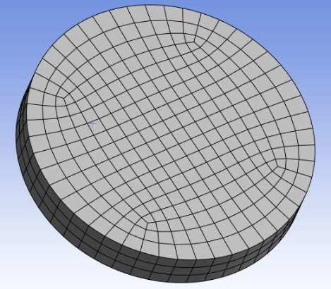
Circle: Creates an O-grid for circular or elliptical type face.
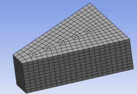
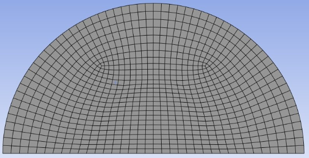
Half-Circle: Creates a C-grid for semi-circular or semi-elliptical type face.
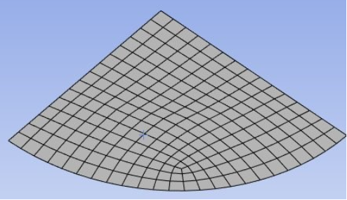
Quarter-Circle: Creates an L-grid for quarter-circle or quarter-ellipse type faces.