


Multizone Method Control provides automatic decomposition of geometry into mapped (sweepable) regions and free regions. When you select Multizone Method Control, all regions are meshed with a pure hexahedral mesh if possible. To handle cases where a pure hex mesh is not possible, you can adjust your settings to generate sweep mesh in the structured regions and a free mesh in unstructured regions.
For example, using the Sweep mesh method, you would need to slice the part below into five bodies as shown to obtain a pure hex mesh:
Note: This section describes method control settings. See MultiZone Meshing for detailed algorithm and usage information.
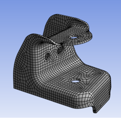
In contrast, using MultiZone requires no slicing. MultiZone automates the geometry decomposition and generates the pure hex mesh shown in Figure 96: MultiZone Generates Pure Hex Mesh without Slicing.
When you select the MultiZone mesh method, the Details View expands to expose various settings, including several that are unique to MultiZone. For basic usage that involves obtaining a MultiZone mesh, the procedure is to apply a Method Control to one or more bodies, set Method to MultiZone, and accept the default values of the various settings.
For advanced or specialized usage, adjust the settings as needed. MultiZone Method Details view has the following options:
Scope
Scoping Method: Allows you to scope geometry or named selection. The default value is Geometry Selection. The available options are:
Geometry: Allows you to scope the geometry for MultiZone method.
Named Selection: Allows you to scope the available named selections for MultiZone method.
Definition
Suppressed: Allows you to suppress the method control. The default value is No. When Suppressed is set to Yes, the Active field is available. Active is a read only field and provides the number of suppressed parts.
Method: Allows you to select the method.
Decomposition Type: Allows you to define the decomposition type. The available options are Program controlled , Thin Sweep, Cart Sweep and Standard. The default option is Program controlled.
Program Controlled: Determines automatically the decomposition type for each body and meshes them accordingly. Program Controlled first mesh all axisymmetric bodies, then mesh thin bodies using MultiZone Thin Sweep and mesh the rest of the bodies with MultiZone Standard option.
Note: Program Controlled does not support cart sweep bodies. You may have to mesh the cart sweep bodies separately using MultiZone Cart Sweep.
Thin Sweep: Detects sweep source and target surfaces and creates the 2D blocking on the source surface. Then, pulled to 3D and associated to the target surfaces in an automatic fashion. You should apply Thin Sweep Decomposition to mesh geometries identified as thin-walled solids, as an alternative to using the typical approach with Standard method. You can use the Select Source/Target Faces tool to select the sweep surfaces.
Note: Partial selection of source and target faces may return partial and inconsistent mesh. Hence, full selection of sources and targets is recommended.
When you select Decomposition Type as Thin Sweep, the Sweep Thickness is available.
Sweep Thickness: Allows you to provide the thickness of the model. The default value is 0. If the value is 0, the application identifies the thickness automatically. If the mesh fails, you may have to provide the thickness. For models with varying thickness, you should provide thickness value slightly greater than the maximum thickness of the model. If you select the sweep source (top) and target (bottom) surfaces, the Thickness value is not used. You can parametrize Sweep Thickness.
Note: The software automatically recognizes the source, side and target faces, then meshes the source set of faces and pulls the sheet blocking to the target set of faces. If the source, side, and target faces cannot be detected correctly, you receive a warning message to select the source or target faces manually.
When no side or only one side of the solid is selected, the following priority is used to determine which (non-thin) side of the solid is a sweep source:
manually selected faces
shared faces or faces with input mesh
non-smooth faces
faces containing more features
faces with the largest area
The software attempts to automatically determine the side faces and remaining faces are the target set of faces.
Alternatively, select the source and target set of faces as the source faces. This should be two sets of connected faces. The remaining faces will be treated as side faces.
Refer Thin Sweep Limitations to view the limitations for Thin Sweep method in MultiZone.
Cart Sweep: Applied to geometries that are axis aligned. Cart Sweep generates a Cartesian mesh, convert that Cartesian mesh to sweepable topologies and smooth it out.
For non-aligned geometries, you can define the sweep direction by selecting a face normal to the sweep direction. Use the Select Source/Target Faces tool to set the sweep direction.
Note: Non-aligned geometries may require additional sizing adjustments when compared to those aligned to the global coordinate system.
You can set up a mapped mesh control on the source face to create all mapped blocks with the Cart Sweep method. The performance (time of mesh generation) depends on two points:
Time to generate the Cartesian mesh depends on the Element Size and Cartesian Size.
Time to convert from Cartesian to sweepable topology depends on the number of topological blocks or bodies created. Many stairsteps can slow things down. So, setting reasonable sizes and defeaturing non-axis-aligned features helps to improve performance.
When setting up the model, ensure that the sizes specified are appropriate for capturing the features. Unlike other mesh methods, reducing the Element Size may cause the mesh to fail. You should use Element Size to define the final mesh sizes.
When you select Decomposition Type as Cart Sweep, the Cartesian Size is available.
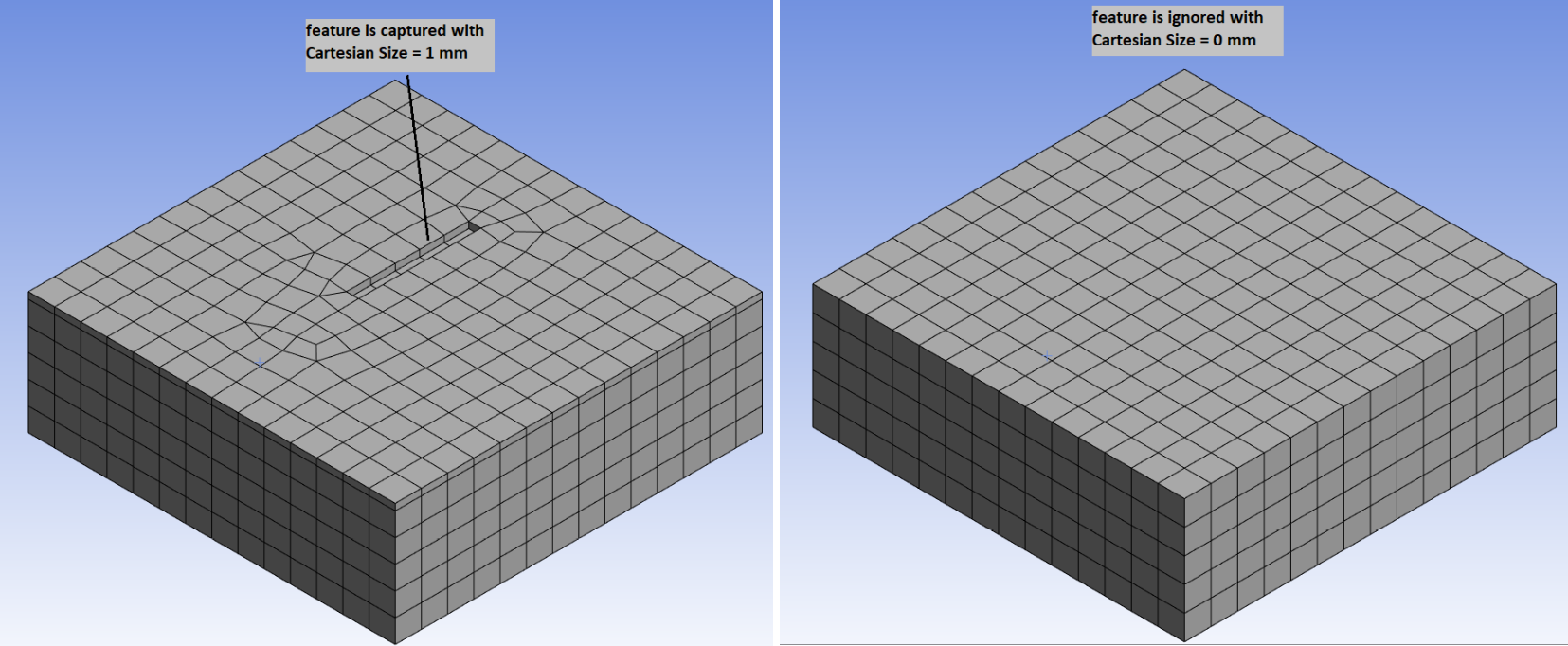
Cartesian Size: Defines the size above which features are captured in the mesh. Here, defeaturing is done based on Cartesian Size. You can set an explicit cartesian size to define the size that the Cartesian mesher uses to capture features. Use a smaller Cartesian mesh size to capture features without increasing final mesh size. If Cartesian Size is default, then mesh size will be used.
Note:Removing fillets or chamfers helps to improve success of meshing.
For selective meshing workflows, first mesh the bodies using the Cart Sweep method and then proceed to mesh the other bodies. The Cart Sweep method does not support pre-meshed adjacent bodies.
Planar surface patches can be preserved with the Cart Sweep method by creating named selection. The Named Selections should include ''protected'' (case-insensitive) as a prefix or suffix to the name (for example, PROTECTED-SIDE, ProtectedFaces, protected-outlet).
Refer Cart Sweep Limitations to view the limitations for Cart Sweep Method in MultiZone.
Spacing Options: Allows you to force split lines to better capture the model features. You can select the following options:
Uniform: Uses the specified element size for spacing.
Key-Points: Check all vertices in the model and add split lines to follow the features, within the specified Key-Points Tolerance. It adjusts the mesh spacing between neighboring split lines so that the hex mesh follows the features. This aligns the cartesian mesh with feature lines and avoids clustering. When you select Key-Points, the Key-Points Tolerance is available and merges the nodes within the provided tolerance. The Key-Points Tolerance value should be less than or equal to the Cartesian Size. If you provide a Key-Points Tolerance value more than the Cartesian Size, the Key-Points Tolerance value gets reset to Cartesian Size.
Note: Key-Points are the corner points of the features. Specifying Key-Points matches cartesian splits with the corner points so that the feature is respected.
Standard: Uses the standard MultiZone Algorithm for meshing which performs a surface blocking and attempts to break the volume into sweepable regions. If the software cannot find any sweepable regions,generates a free mesh.
Mapped/Swept Mesh Type: Determines the shape of the elements used to fill structured regions. The default is . The available options are:
: Generates a mesh of all hexahedral elements for the part the method is scoped to.
: Generates a mesh of hexahedral and prism or wedge elements for the part the method is scoped to. The main difference between the option and Hexa is that for swept regions, the surface mesh can allow triangles for quality and transitioning. The triangles are later extruded to prisms or wedges.
: Generates a mesh of all prism elements is generated for the part the method is scoped to. This option is sometimes useful if the source face mesh is being shared with a tet mesh, as pyramids are not required to transition to the tet mesh.
Surface Mesh Method: Instructs MultiZone to use the , , or method to create the surface mesh. The default method is .
: Automatically uses a combination of and mesh methods depending on the mesh sizes set and face properties.
Note: When you mesh a surface with more than thousand patches, Program Controlled automatically uses Prime Quad Dominant Method for meshing.
: Uses a recursive loop-splitting method which creates a highly uniform mesh. Uniform method is used when all edges have the same sizing and the faces being meshed do not have a high degree of curvature. This method provides good orthogonal mesh.
: Uses a paving mesh method which creates a good quality mesh on faces with high curvature, when neighboring edges have a high aspect ratio. This approach is also more reliable to give an all-quad mesh.
Note: The Surface Mesh Method is applicable only to faces that are free meshed. If a face can be mapped meshed, it will be. See Face Meshing Control for more information.
Free Mesh Type: Instructs MultiZone to allow a free mesh if it is not possible (without slicing) to generate a pure hex or hex/prism mesh. Free Mesh Type is available only when the Decomposition Type is Standard. The value of Free Mesh Type determines the shape of the elements used to fill unstructured regions. The default is . The available options are:
: Choose this option if you require a mapped mesh.
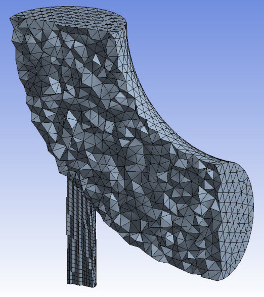
: Fills tetrahedral mesh on the regions of the model that cannot be meshed with a mapped mesh. Figure 97: Free Mesh Type = Tetra shows a MultiZone mesh that was generated when Free Mesh Type was set to . Notice the lower section is mapped meshed, and the upper section is free meshed because it cannot be map meshed. Refer to Patch Conforming Algorithm for Tetrahedrons Method Control for more information.
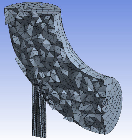
: Fills tetrahedral mesh with pyramids at the faces on the regions of the model that cannot be meshed with a mapped mesh will be filled with a tetrahedral mesh with pyramids at the faces. Figure 98: Free Mesh Type = Tetra/Pyramid shows a MultiZone mesh that was generated when Free Mesh Type was set to . Notice the lower section is mapped meshed, and the upper section is free meshed because it cannot be map meshed. Refer to Patch Conforming Algorithm for Tetrahedrons Method Control for more information.
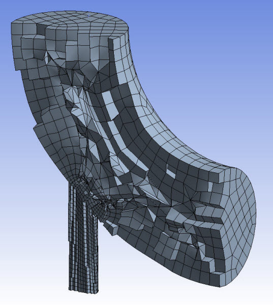
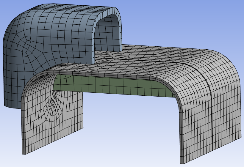
: Fills hex dominant mesh on regions of the model that cannot be meshed with a mapped mesh. Figure 99: Free Mesh Type = Hexa Dominant shows a MultiZone mesh that was generated when Free Mesh Type was set to . Notice the upper section is mapped meshed, and the lower section is free meshed because it cannot be mapped meshed. Refer to Hex Dominant Method Control for more information.
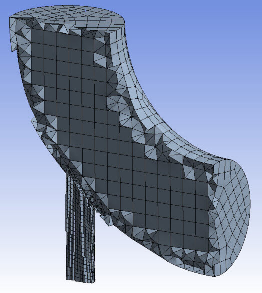
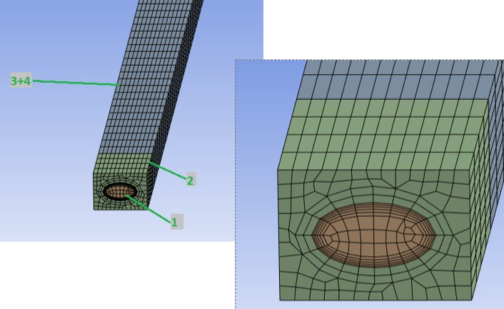
: Fills hexa core mesh on the regions of the model that cannot be meshed with a mapped mesh. Hexa Core meshes can be generated where most of the volume is filled with a Cartesian array of hexahedral elements replacing the tetras. This is connected to the remainder of a prism/tetra hybrid by automatic creation of pyramids. Hexa Core allows for reduction in number of elements for quicker solver run time and better convergence. Figure 100: Free Mesh Type = Hexa Core shows a MultiZone mesh that is generated when Free Mesh Type was set to . Notice the upper section is mapped meshed, and the lower section is free meshed because it cannot be mapped meshed.
Element Order: Refer to Method Controls and Element Order Settings. The default is .
Src/Trg Selection: Defines the source and target selection type. The default is . The available options are:
: Determines the source and target automatically. The option works fine for simple sweep configurations, but if there are multiple levels of sweeps, it is often best to manually define the source faces.
: Allows you to select the faces to be used as sources (and targets) using the specifiedSource(s) and Target(s). MultiZone treats all sources or targets as sources, as imprinting can occur from either side. For more details, refer to the description of Src/Trg Scoping Method, Source(s) and Target(s), and Src/Trg Named Selection below.
Src/Trg Scoping Method: Defines the method for choosing a source face. Geometry Selection enables you to select sources or targets manually using the Source(s) and Target(s) option. Named Selection enables you to choose one Named Selection as a source or target using the Src/Trg Named Selection option.
Source(s) and Target(s): Select the faces that need to be imprinted for proper geometry decomposition. Source(s) and Target(s) is available when you select Geometry Selection as your Src/Trg Scoping Method. The faces you select can be either "sources" or "targets," but all of them are treated as sources by MultiZone, as shown in Figure 101: Source / Target Face Selection for MultiZone.
Note: To make source face selection easier, select from the Toolbar and then deselect Body Scoping Annotations in the Annotation Preferences option box to toggle the visibility of annotations in the Geometry window. For example, after scoping MultiZone to a body, the body is displayed using a blue solid annotation. Turn off the body scoping annotations, then select the source faces. For picking internal faces, the Hide Faces right-click option may help you to see inside a body. For example, you can select external faces in the Geometry window and then use the Hide Faces option to hide the selected faces (making it easier to select the internal faces).
Src/Trg Named Selection: Choose an existing named selection to select the faces that need to be imprinted for proper geometry decomposition. Src/Trg Named Selection is only available when you select Named Selection as your Src/Trg Scoping Method.
Sweep Size Behavior: Enables you to set a Sweep Element Size to define the mesh spacing (default), or to select Sweep Edges to remove edges and prevent them from constraining the source faces.
Sweep Element Size: Enables you to set an element size to define the mesh spacing along the sweep path from source to target faces. If this control is set to a non-zero value, sizing controls applied to the selected bodies as curvature and proximity refinement, local sizing or both are ignored.
The Sweep Element Size setting is ignored if hard size controls are applied to side edges or faces. If multiple bodies with the same sweep direction have different sizes set for Sweep Element Size, the smallest size is used and the others are ignored.
Selecting the check box adds Sweep Element Size to the Workbench parameters, enabling you to use element size settings as a variable design point when creating multiple solutions.
Sweep Edges: This option should be used with an edge sizing control. The edge sizing control defines the distribution along the sweep path, and can also affect the source face. Use this option to remove the influence of the edge sizing from the source face mesh. That is, the edges selected will only influence the sweep path and not the source faces.
Sweep Number of Divisions: Allows you to provide the number of elements across the thickness. Available only when the Decomposition Type is Thin Sweep. Sweep Number of Divisions is not respected for cases where walls (side faces) are shared with source or target surfaces of connected bodies. You can parametrize Sweep Number of Divisions.
Element Option: Allows you to select the element type for the solver to use. The available options are Solid and Solid Shell. The default value is Solid. Element Option is available only when the Decomposition Type is Thin Sweep.
Note: In Sweep Method control, Automatic Thin and Manual Thin provide better orthogonal quality mesh than MultiZone Thin Sweep for Solid Shell element option for models with slanted side faces.
Preserve Boundaries: Preserves only the protected topologies (See Protecting Topology Defined Prior to Meshing) or all features in the model. The default value is Protected. The available options are:
Protected: Preserves only the protected topologies at the boundary.
All: Preserves all topologies at the boundary.
Mesh Based Defeaturing: Filters edges in or out based on size. The default value is Off. If set to On, a Defeature Size field appears where you may enter a numerical value greater than 0.0. By default, the value of this local Defeature Size field is the same as the global Defeature Size. If you specify a different value here, it overrides the global value. Specifying a value of 0.0 here, resets the tolerance to its default. Available only when the Decomposition Type is Standard and Thin Sweep.
Minimum Edge Length: Read-only indication of the smallest edge length in the model.
Write ICEM CFD Files: Sets options for writing Ansys ICEM CFD files. Refer to Writing Ansys ICEM CFD Files for details. The default is No.
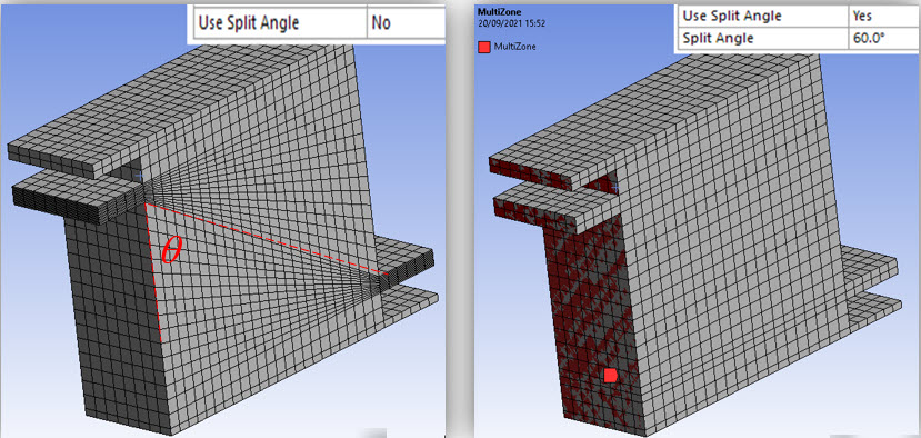
Use Split Angle: Decomposed regions are sent in blocks to the meshing algorithm. This option splits the edges of the decomposed regions to improve the mapped mesh quality and prevent skewed mesh on side faces. The default option is No. For Physics Preference set to Explicit, the default option is Yes. If the mesh is skewed, you can set the Use Split Angle to Yes to create new region splits which will create more orthogonal mesh. When Use Split Angle is set to Yes, the Split Angle is enabled and allows you specify the value for the split angle. The default value is 60 degrees. The splits are created at nodes where the angle of an end node of an edge (edge vector) to the corresponding end node of a parallel edge is less than the specified split angle. Use Split Angle is available only when the Decomposition Type is Standard.
Note: For detailed information about MultiZone, refer to MultiZone Meshing. For general information on applying MultiZone in combination with other mesh method controls, refer to Meshing: Mesh Control Interaction Tables.
Notes on Scoping for the MultiZone Mesh Method
You can use the MultiZone mesh method in combination with other solid mesh methods in a multibody part, and the bodies are meshed with conformal mesh.
If a multibody part contains some bodies that are scoped to be meshed with MultiZone and other bodies that are not scoped with any mesh method, then the other bodies are meshed with the default mesh method.
Refer to Conformal and Non-Conformal Meshing for information about conformal meshing.
For Torus geometry with sliver faces, set Mesh Based Defeaturing as ON to avoid mesh failure.
MultiZone supports handling bodies where all three Decomposition Types are applied on different bodies. When you mesh multibodies with shared topology simultaneously, all bodies with Cart Sweep applied are meshed first, followed by bodies applied with Thin Sweep and finally the bodies applied with Standard MultiZone.
MultiZone tries to mesh axisymmetric cases using the Standard Decomposition Type. In case of failure, set the Defeature Size other than the default value. This forces the application to create a revolved profile blocking. This feature requires that all faces in the body to be 360 degree fully revolved but edges could be split. It does not support cases with cutouts in the revolved surface.
For long coil cases failure,you may perform the following:
If the geometry is unclean, save the geometry in ACIS format and import the geometry to SpaceClaim and save the database. Slice one end of the coil into a small piece. Now, apply Shared topology and clean up the geometry using Repair and Prepare tools in SpaceClaim and save the database. Open the saved database in the Mesh component system in Ansys Workbench and apply mesh setting and perform meshing.
Selective meshing may help sometimes. For example, mesh the inner body first, followed by the outer body and then two long bodies along the length of the coil simultaneously.
Thin Sweep Limitations
The limitations of Thin Sweep are:
Thin Sweep does not fully support multibody part with shared topology meshed either with all bodies once or selective meshing.
Thin Sweep does not support intersecting loops in double side imprinting.
When you try to mesh all bodies in a model having a stack of the thin bodies, Thin Sweep may not recognize the bodies as thin bodies.
The Sweep Number of Divisions is not respected for cases where walls (side faces) are shared with source or target surfaces of connected bodies. In the below example, the Sweep Number Of Divisions = 2 is not respected for top body.
Cart Sweep Limitations
The limitations of Cart Sweep are:
Cart Sweep supports Mapped Mesh Type only with source face selection.
Cart Sweep supports only Preserve Boundaries that are Protected.
Cart Sweep may not work well with shared topology.