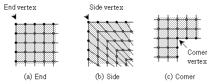
To use advanced mapped Face Mesh controls on a face, you must do the following:
Select the face upon which the vertex types are to be defined
Select the vertex type (using the Specified Sides, Specified Corners, and Specified Ends controls)
Pick the vertices to which the vertex type specification is to be applied
Selecting the Face
The Meshing application vertex types are specific to the faces upon which they are set. Therefore, to specify the type designation of an individual vertex, you must first select a face to be associated with that vertex. An individual vertex may possess as many vertex type designations as the number of faces to which it is attached. For example, it is possible for a vertex to possess a Side type designation with respect to one face and an End type designation with respect to another, as long as two separate mapped face meshing controls are defined for the two faces. For more information, refer to Setting Advanced Face Meshing Controls for Mapped Meshing.
Selecting the Vertex Type and Picking Vertices
The structure of any face mesh in the vicinity of an individual vertex on its boundary is a function of the vertex type. There are three vertex types that you can specify.
End
Side
Corner
An individual vertex may possess only one vertex type designation. For example, you cannot designate a vertex as type "side" and also designate that same vertex as type "end." For more information, refer to Setting Advanced Face Meshing Controls for Mapped Meshing.
Each vertex type differs from the others in the following ways:
The number of face mesh lines that intersect the vertex
The angle between the edges immediately adjacent to the vertex
The following table summarizes the characteristics of the vertex types shown in Figure 106: Face Vertex Types.
Note: If a face has only 4 vertices and 4 edges, the maximum for the range of the angle of a Side vertex type is 179°, and the acceptable range shifts accordingly.
| Vertex Type | Intersecting Grid Lines | Range of Angle Between Edges |
|---|---|---|
| End | 0 | 0° — 135° |
| Side | 1 | 136° — 224° |
| Corner | 2 | 225° — 314° |
| Reversal | 3 | 315° — 360° (You cannot specify Reversal vertices. The range for Reversal vertices is used internally by the Meshing application to determine whether the face is mappable.) |
The following sections describe the general effect of the End, Side, and Corner vertex types on the shape of the face mesh in the vicinity of a specified vertex.
- End Vertex Type
When you specify a vertex as the End vertex type (Specified Ends control), the Meshing application creates the face mesh such that only two mesh element edges intersect at the vertex (see (a) in Figure 106: Face Vertex Types). As a result, the mapped and submapped face mesh patterns on both sides of the End vertex terminate at the edges adjacent to the vertex. Assigning the End vertex type to a vertex whose adjacent edges form an angle greater than 180° will likely result in mesh failure.
- Side Vertex Type
When you specify a vertex as the Side vertex type (Specified Sides control), the Meshing application creates the face mesh such that three mesh element edges intersect at the vertex (see (b) in Figure 106: Face Vertex Types). The Meshing application treats the two topological edges that are adjacent to the vertex as a single edge for the purposes of meshing.
- Corner Vertex Type
When you specify a vertex as the Corner vertex type (Specified Corners control), the Meshing application creates the face mesh such that four mesh element edges intersect at the vertex (see (c) in Figure 106: Face Vertex Types). Assigning the Corner vertex type to a vertex whose adjacent edges form an angle less than 180° will create an unnecessarily bad quality mesh (although the mesh will be valid).


