When an imprint is made to connect two sets of source faces, side faces are constructed in the process. (See Figure 150: Classifying the Problem: Handling of Paths and Imprints.) Generally, the pairs of imprints create a natural set of side faces that are mappable. However, if there are several sets of side faces along the sweep path, the interval edge assignment of the internal mapped faces can become tricky. Because there are not physical faces or edges to help define the interval edge assignment, you are sometimes better off adding more decomposition to help control this (either by splitting some of the external faces, or by slicing the geometry).
The simple cutout case shown below illustrates this.
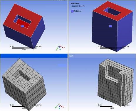
In the case above, there is a set of source faces at top, center, and bottom. Internal side faces are constructed from the center to the bottom and the interval edge assignment for these internal edges is found by subtracting the number of divisions for the top to center region of sweep path from the entire sweep path.
However, in cases in which the internal cutouts are at multiple levels or the sides do not provide a clear connected path, MultiZone could have difficulties constructing side faces with appropriate interval edge assignment unless you set the Free Mesh Type to something other than , or you perform manual geometry decomposition. Refer to the figure below for an example showing cutouts at multiple levels.
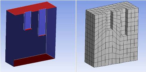
In the figure above, notice that cutouts at different levels are meshed at the same level with regard to the grid lines.
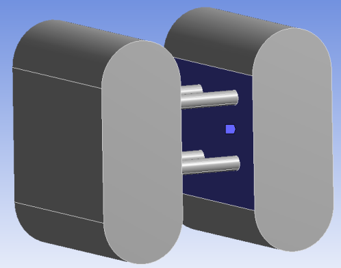
When there are intersections between the imprints and the side faces along the sweep path, some complications may arise. For example, the case shown in Figure 165: Intersections Between Levels and Sides has one clear sweep path (top to bottom), six levels (sets of sources), and a need for imprints.
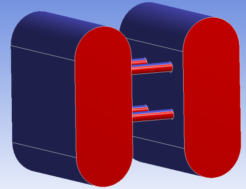
The legend below explains the symbols and display options used in Figure 165: Intersections Between Levels and Sides.

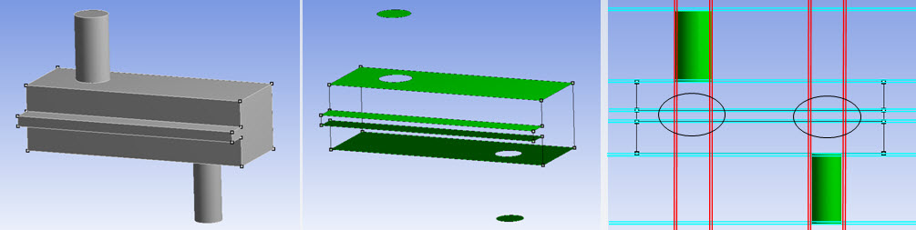
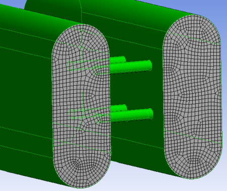
To construct a swept mesh on this model, MultiZone needs to resolve the intersections between the cylinders, and the side rib. In this case, meshing is successful because the sources are well-defined, and the side face handling is clear (side faces can be submapped appropriately).
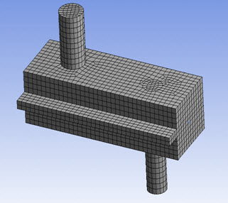
However, if the sources are not well-defined (or incomplete), or the side faces cannot be mapped, MultiZone will have difficulties. To fix such problems, add extra decomposition or mesh with the Free Mesh Type option.
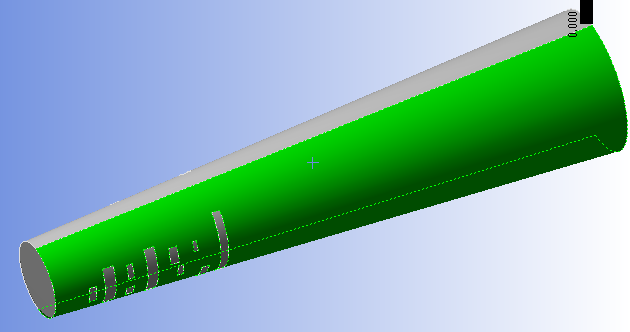
Cylindrical Side Faces
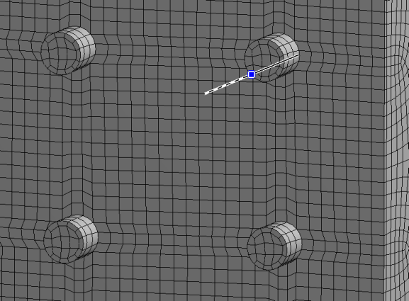
Cylinders have a start and end point which, at times, can affect the quality of the meshing. When you add a first virtual edge to split a circle (the side face of a cylinder), you create two vertices: one where you split the circle and one at the end point, as shown below.
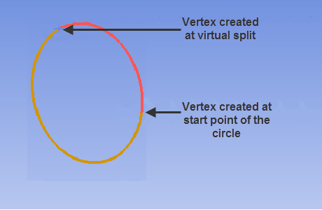
If MultiZone fails to mesh a cylindrical surface with cut-outs folded at greater than 180 degrees, splitting the cylinder along the seam to get a sub-mapped face mesh may help. If you use this method, check to ensure that the split does not hamper mesh quality.
For more information about virtual split edges, see Creating and Managing Virtual Split Edges.
Internal Loop Side Faces
When internal loops exist along the side faces of the sweep path, as shown in Figure 169: Internal Loops along Side Faces of the Sweep Path below, the following tips might help:
Assign a mapped face control to the side face(s) with the internal cutouts to help ensure those faces are mapped.
Assign front/back of connecting faces as source faces for MultiZone.
If side faces are cylindrical, use inflation to get reasonable quality mesh.