


Many engineering systems, including power plants, climate control, and engine cooling systems typically contain tubular heat exchangers. However, for most engineering problems, it is impractical to model individual fins and tubes of a heat exchanger core. In principle, heat exchanger cores introduce a pressure drop to the primary fluid stream and transfer heat from or to a second fluid (for example, a coolant), referred to here as the auxiliary fluid.
Ansys Fluent provides two distinct methods of modeling a heat exchanger: the dual cell model and the macro model. These models can be used to compute the auxiliary fluid inlet temperature for a fixed heat rejection or the total heat rejection for a fixed auxiliary fluid inlet temperature. The dual cell model allows the solution of the passes of the auxiliary flow on a separate mesh, that is, other than the primary fluid mesh (see Figure 16.60: An Example of a Four-Pass Heat Exchanger), unlike the macro model, where the auxiliary flow passes are modeled as 1D flow.
Important: Note that the heat exchanger models are not appropriate for modeling a cold-only flow; in such a case, you should instead use the porous media model, as described in Porous Media Conditions.
For theoretical information about the various heat exchanger models, refer to Heat Exchangers in the Theory Guide.
The following sections contain information about the heat exchanger models:
Ansys Fluent provides various options for modeling heat exchangers, each with their own features and limitations. The following instructions can help you determine which option/combination of options is the most appropriate for your problem.
Decide whether you want to use the dual cell model or the macro model.
The dual cell model provides the greatest flexibility with regard to the shape of the heat exchanger core and the nature of the mesh, and allows the auxiliary fluid to be highly non-uniform as it enters the core (for example, due to passing through arbitrary shaped inlet tanks). However, the dual cell model may need to be discounted as an option because of the following limitations:
If the heat exchanger performance data that you have is in the form of a velocity vs. effectiveness curve, the dual cell model cannot be used.
The dual cell model does not allow you to model phase change in the auxiliary fluid.
If the previous limitations are not relevant for your problem, you can proceed directly to using the dual cell model, as described in Using the Dual Cell Heat Exchanger Model.
While the macro model has more restrictions than the dual cell model, it is quite suitable for a thin 3D heat exchanger core with a rectangular cross-section, where the pass-to-pass plane is perpendicular to the primary flow direction, the auxiliary flow is uniform (so it can be treated as a 1D flow), and the mesh is uniform and structured. To verify that your problem can tolerate the limitations of the macro model, see Restrictions.
If you chose to use the macro model in the previous step, you must decide whether you want to use the grouped or ungrouped version of this model. If you want to define a single heat exchanger using multiple fluid zones, or if you would like to connect the fluid flow path among multiple heat exchangers, you should use the grouped version, as described in Using the Grouped Macro Heat Exchanger Model. Otherwise, you can use the ungrouped version, as described in Using the Ungrouped Macro Heat Exchanger Model.
If you chose to use the macro model in the step 1., you must decide whether you want to model the heat transfer using the number-of-transfer-units (NTU) method or the simple effectiveness method. This decision largely rests on the kind of experimental data that you have: the NTU method requires that you provide the various primary fluid flow rates and auxiliary fluid flow rates and the corresponding heat transfer values; the simple effectiveness method requires that you provide the data points for a curve that defines how the effectiveness (that is, the ratio of actual rate of heat transfer between the primary and auxiliary fluids to the maximum possible rate of heat transfer) varies with the fluid velocity. Additionally, you should consider the differences between the two heat transfer models outlined in Table 16.1: NTU Model Vs. Simple Effectiveness Model.
Table 16.1: NTU Model Vs. Simple Effectiveness Model
NTU Model Simple Effectiveness Model How many phases are allowed in the auxiliary flow? single phase only single phase and two phase Can you model primary fluid-side reverse flow? Yes No Can the primary fluid have a variable density? Yes No Must the primary fluid heat capacity be less than the auxiliary fluid heat capacity? No Yes You will specify whether you want the NTU or simple effectiveness model in the Model Data tab of either the Ungrouped Macro Heat Exchanger dialog box or the Heat Exchanger Group dialog box, depending on whether you opted for the ungrouped or grouped version of the macro model, respectively.
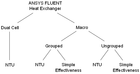
An overview of the options available to you when modeling heat exchangers is shown in Figure 16.61: Heat Exchanger Modeling Options.
The dual cell heat exchanger model allows the solution of both the primary and auxiliary flow on separate co-located meshes and couples the two flows only through heat transfer at the heat exchanger core.
For theoretical information about this model, refer to The Dual Cell Model in the Theory Guide.
The following restrictions exist for the dual cell heat exchanger models:
The simple effectiveness model is not available.
The heat exchanger performance data must be in the form of heat transfer rates or number of transfer units (NTU) for auxiliary / primary fluid flow rate combinations, rather than a velocity vs. effectiveness curve.
In the case of a heat exchanger in which the primary and auxiliary meshes are not identical, heat transfer may be non-conservative (that is, the heat lost by the hot fluid may not equal the heat gained by the cold fluid). To minimize the difference in heat transfer, the topology and size of the primary and auxiliary cells should be as similar as possible, with the ideal being one-to-one cell conductivity. Note that you can make the meshes identical by copying a zone via the
mesh/modify-zones/copy-move-cell-zonetext command.
The steps for setting up the dual cell heat exchanger model is as follows:
Read the mesh file.
If the mesh file does not already contain overlapping heat exchanger cores for primary and auxiliary fluids, then you must create a duplicate of the zone that represents the core using the following text command:
mesh→modify-zones→copy-move-cell-zoneSee Copying Cell Zones for details on copying meshes.
Make sure that the auxiliary fluid mesh is divided into separate zones, one for each pass.
 Domain
→ Zones
→ Separate
→ Cells...
Domain
→ Zones
→ Separate
→ Cells...
See Separating Cell Zones for details on separating meshes.
Make sure that the inlet and outlet for the heat exchanger are two separate zones.
Enable the calculation of energy in the Energy dialog box.
 Setup →
Models → Energy
Setup →
Models → Energy
 ON
ON
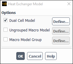
Enable the Dual Cell Model in the Heat Exchanger Model dialog box and click (Figure 16.62: The Heat Exchanger Model Dialog Box).
Setup →
Models → Heat
Exchanger Edit...
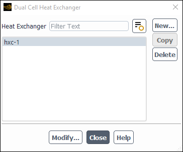
Specify the inputs to the dual cell heat exchanger model, using the Dual Cell Heat Exchanger dialog box (Figure 16.63: The Dual Cell Heat Exchanger Dialog Box).
Click to define the heat exchanger. The Set Dual Cell Heat Exchanger dialog box will appear (Figure 16.64: The Set Dual Cell Heat Exchanger Dialog Box), where you will define the heat exchanger parameters.
Enter the heat exchanger Name or keep the default name. The suffix
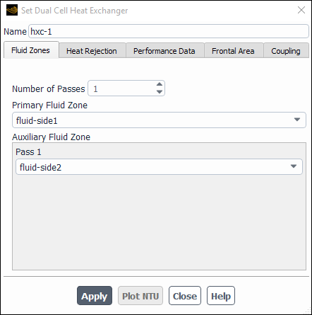
-1is incremented automatically on defining more than one heat exchanger.In the Fluid Zones tab (Figure 16.64: The Set Dual Cell Heat Exchanger Dialog Box)
Specify the Number of Passes of your heat exchanger.
Select the appropriate Primary and Auxiliary Fluid Zone, representing the heat exchanger core.
Important: The selected zones must be overlapping in physical space.
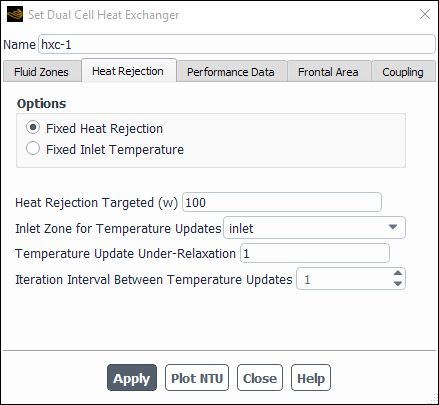
Click the Heat Rejection tab (Figure 16.65: The Heat Rejection Tab).
If you select Fixed Heat Rejection, set the inputs for the following:
Heat Rejection Targeted which is the heat rejection desired from the heat exchanger.
Inlet Zone for Temperature Updates allows Ansys Fluent to change the temperature of the specified inlet zone in order to match the targeted heat rejection.
Temperature Update Under-Relaxation is a factor that controls convergence.
Iteration Interval Between Temperature Updates is used to control divergence.
Select Fixed Inlet Temperature if the output desired is total heat rejection.
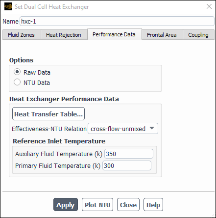
Click the Performance Data tab (Figure 16.66: The Performance Data Tab).
You must decide whether you will select Raw Data or NTU Data from the Options list. Using the Raw Data option specifies that the effectiveness (
 ) is evaluated as the ratio of the rate of heat
transfer between the primary and auxiliary fluids (which you
define in a table format) to the maximum possible rate of heat
transfer (
) is evaluated as the ratio of the rate of heat
transfer between the primary and auxiliary fluids (which you
define in a table format) to the maximum possible rate of heat
transfer ( ) for the current flow regime (see Equation 6–7 in the Theory Guide).
The calculated efficiency is then used to calculate the NTU
value using the crossflow formula for each and every set of
primary and auxiliary flow rates.
) for the current flow regime (see Equation 6–7 in the Theory Guide).
The calculated efficiency is then used to calculate the NTU
value using the crossflow formula for each and every set of
primary and auxiliary flow rates.If the heat exchanger manufacturer used a similar approach in evaluating the NTU values, then there is no difference between the Raw Data and NTU Data options. However, if a different methodology was used by the manufacturer that accounts for some possible non-uniformity of the profile or for the partial mixing of the flow stream, then the NTU Data option is likely to be more accurate. Similarly, you may be able to assess more accurate NTU values for your case using tables from the relevant literature. This can even include some mixing of the oncoming flow stream, for situations where the primary flow can deviate from the direction normal to the heat exchanger tubes; this can happen in heat exchangers where the fins are either very spaced or absent. Therefore, the NTU Data option can be more accurate if the NTU values are gathered at non-ideal conditions that bear a close resemblance to your simulated scenario.
If you select the Raw Data option, then specify the following:
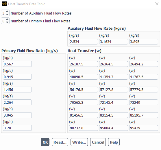
Heat Transfer Data... opens the Heat Transfer Data Table Dialog Box, where you will enter experimental data that defines how heat transfer values relate to the fluid flow rates (Figure 16.67: The Heat Transfer Data Table Dialog Box). See Specifying Heat Exchanger Performance Data more details.
Effectiveness-NTU Relation computes the NTU values from the heat transfer data. Choose cross-flow-unmixed, parallel-flow, or counter-flow, all of which are described in NTU Relations.
Auxiliary Fluid Temperature is the inlet reference temperature for the auxiliary fluid.
Primary Fluid Temperature is the inlet reference temperature for the primary fluid.
If you select the NTU Data option, click to access the NTU Table dialog box. Populate this table in the same manner as described previously for the Heat Transfer Data Table Dialog Box. More information is available in Specifying Heat Exchanger Performance Data.
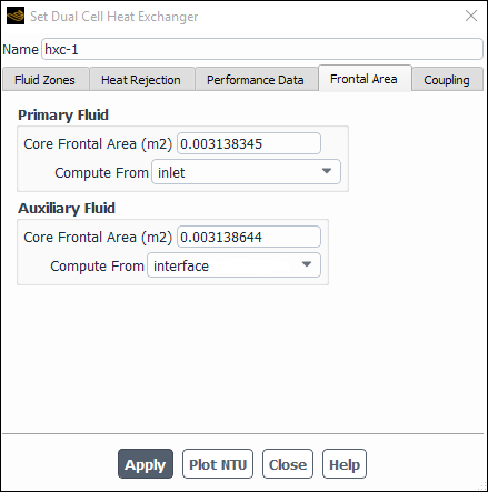
Click the Frontal Area tab. You have the option to specify the Primary and Auxiliary Fluid Core Frontal Area directly, or compute the area from a surface zone, as shown in Figure 16.68: The Frontal Area Tab.
Note: For a multipass configuration, you only need to specify the frontal area of a single pass, for a fluid which is being routed through such passes. This can be applicable either to an auxiliary fluid, primary fluid, or to both of them, depending on the flow arrangement through the core of a heat exchanger.
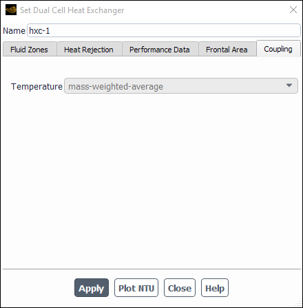
Click the Coupling tab if you want to couple the heat exchanger passes (Figure 16.69: The Coupling Tab).
Consider the following example illustrating the coupling of a four-pass heat exchanger.
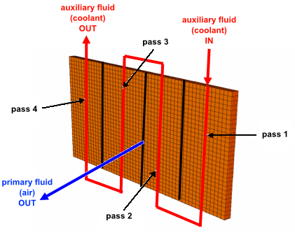
Figure 16.70: An Example of a Four-Pass Heat Exchanger shows a four-pass heat exchanger with air as the primary fluid and the coolant as the auxiliary fluid. The coolant flows through the tubes in a serpentine manner and air flows normal to the tubes, forming a cross flow pattern. To model this type of flow using the dual cell heat exchanger model, you must first generate the mesh. The mesh should contain the following:
A single primary cell zone.
Four adjacent auxiliary cell zones, one for each pass. Each auxiliary zone should be separated from the other by a coupled or uncoupled wall. Each pass will have its own inlet and outlet zones.
The primary and four auxiliary zones should overlap in physical space.
In the Coupling tab, mass-weighted-average is selected by default for the Temperature of the outlet of Pass 1 to the inlet of Pass 2. Similarly, the mass-weighted-average temperature of the outlet of Pass 2 will be applied at the inlet zone of Pass 3, and so on. Alternatively, you can couple the passes by using Profiles... in the Boundary Conditions task page or by using user-defined functions to define the Temperature in the Thermal tab of the relevant boundary condition dialog boxes. If you do so, make sure you select none from the Temperature drop-down list in the Coupling tab of the Set Dual Heat Exchanger dialog box.
Important: Make sure to specify the auxiliary zones in the correct order (that is the zone for Pass 1 should be selected first, then Pass 2, and so on) in the Fluid Zones tab of the Set Dual Cell Heat Exchanger dialog box.
Click to save the heat exchanger inputs.
To view the plot of NTU vs. primary mass flow rate for each auxiliary mass flow rate, click .
The button will plot the performance data curve for the selected heat exchanger. The performance data is supplied through the Performance Data tab.
When you close the Set Dual Cell Heat Exchanger dialog box, you will return to the Dual Cell Heat Exchanger dialog box, where you should now see the heat exchanger name in the Heat Exchanger list.
You can
Modify the settings of heat exchanger by selecting it from the list and clicking .
Copy the data of one heat exchanger to another using the button, assuming you have more than one heat exchanger.
Delete any unwanted heat exchangers by selecting the heat exchanger from the list and clicking .
Important: All the inputs are copied except for the name, primary fluid zone and auxiliary fluid zone.
To use the macro heat exchanger model, you must define one or more fluid zone(s) to represent the heat exchanger core. Typically, the fluid zone is sized to the dimension of the core itself. As part of the setup procedure, you will define the auxiliary fluid path, the number of macros, and the physical properties and operating conditions of the core (pressure drop parameters, heat exchanger effectiveness, auxiliary fluid flow rate, and so on).
Additional information about macro heat exchangers can be found in Overview of the Macro Heat Exchanger Models in the Theory Guide. For the theory behind these models, refer to Macro Heat Exchanger Model Theory in the Theory Guide.
Ansys Fluent provides two heat transfer models: the default NTU model and the
simple effectiveness model. The simple effectiveness model interpolates the
effectiveness from the velocity vs. effectiveness curve that you provide. For the
NTU model, Ansys Fluent calculates the effectiveness,  , from the NTU value that is calculated by Ansys Fluent from the
heat transfer data provided by you in tabular format. Ansys Fluent will
automatically convert this heat transfer data to a primary fluid mass flow rate vs.
NTU curve (this curve will be piecewise linear). This curve will be used by
Ansys Fluent to calculate the NTU for macros based on their size and primary fluid
flow rate.
, from the NTU value that is calculated by Ansys Fluent from the
heat transfer data provided by you in tabular format. Ansys Fluent will
automatically convert this heat transfer data to a primary fluid mass flow rate vs.
NTU curve (this curve will be piecewise linear). This curve will be used by
Ansys Fluent to calculate the NTU for macros based on their size and primary fluid
flow rate.
The NTU model provides the following features:
The model can be used to check heat capacity for both the primary and the auxiliary fluid and takes the lesser of the two for the calculation of heat transfer.
The model can be used to model heat transfer to the primary fluid from the auxiliary fluid, and vice versa.
The model can be used to model primary fluid-side reverse flow.
The model can be used with variable density of the primary fluid.
The model can be used in either the serial or parallel Ansys Fluent solvers.
The model can be used to make a network of heat exchangers using a heat exchanger group (Using the Grouped Macro Heat Exchanger Model).
Transient profiles can be used for the auxiliary fluid inlet temperature and for total heat rejection.
Transient profiles can be used for auxiliary mass flow rates.
The simple effectiveness model provides the following features:
The model can be used to model heat transfer from the auxiliary fluid to the primary fluid, and vice versa.
The auxiliary fluid properties can be a function of pressure and temperature, therefore allowing phase change of the auxiliary fluid.
The model can be used by serial as well as parallel solvers.
The model can be used to make a network of heat exchangers using a heat exchanger group (Using the Grouped Macro Heat Exchanger Model).
Transient profiles can be used for the auxiliary fluid inlet temperature and for total heat rejection.
Transient profiles can be used for auxiliary mass flow rates.
For additional information, see the following sections:
The following restrictions exist for the macro heat exchanger models:
The core must be a 3D mesh with a cross-section that is approximately rectangular in shape.
The primary fluid streamwise direction (see Equation 6–1 in the Theory Guide) must be aligned with one of the three orthogonal axes defined by the rectangular core.
The pass-to-pass plane must be perpendicular to the primary fluid streamwise direction.
The two dimensions of the pass-to-pass plane can each be discretized into multiple macroscopic cells (macros), but in the direction perpendicular to this plane the macros cannot be subdivided.
It is highly recommended that the free-form Tet mesh is not used in the macro heat exchanger model. Instead, evenly distributed Hex/Wedge cells should be used for improved accuracy and a more robust solution process.
Flow acceleration effects are neglected in calculating the pressure loss coefficient.
For the simple effectiveness model, the primary fluid must have a capacity rate that is less than that of the auxiliary fluid.
Auxiliary fluid phase change cannot be modeled using the NTU model.
The macro-based method requires that an equal number of cells reside in each macro of equal size and shape.
The auxiliary fluid flow is assumed to be 1D.
The pass width has to be uniform.
Accuracy is not guaranteed when the mesh is not structured or layered.
Accuracy is not guaranteed when there is upstream diffusion of temperature at the inlet/outlet of the core.
Non-conformal meshes cannot be attached to the inlet/outlet of the core. An extra layer has to be created to avoid it.
The heat exchanger model settings may be written into and read from the
boundary conditions file (Reading and Writing Boundary Conditions) using the
text commands, file/write-settings and
file/read-settings, respectively. Otherwise, the
steps for setting up the ungrouped macro heat exchanger model is as
follows:
Read the mesh and make sure that the inlet and outlet for the heat exchanger are two separate zones.
Enable the calculation of energy in the Energy Dialog Box.
Setup →
Models → Energy
ON
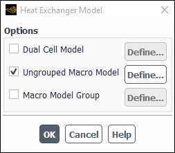
Enable the Ungrouped Macro Model option and click the button in the Heat Exchanger Model Dialog Box (Figure 16.71: The Heat Exchanger Model Dialog Box) to access the Ungrouped Macro Heat Exchanger dialog box.
Setup →
Models → Heat
Exchanger Edit...
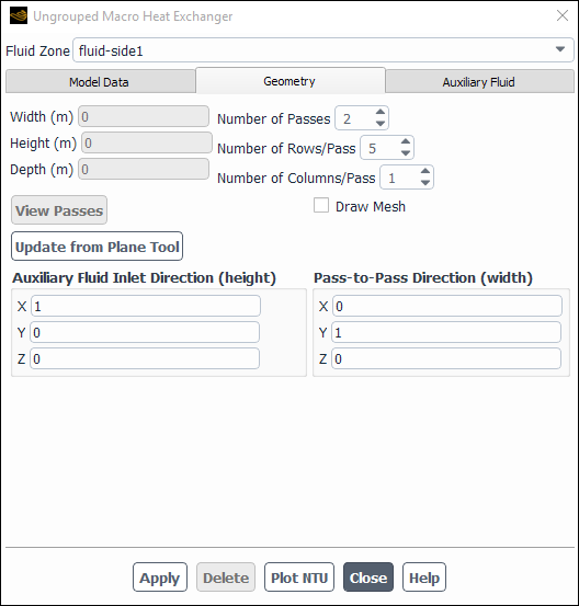
Specify the heat exchanger inputs in the Ungrouped Macro Heat Exchanger dialog box.
In the Fluid Zone drop-down list, select the fluid zone representing the heat exchanger core.
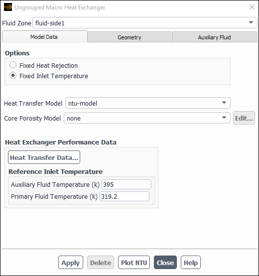
Under the Model Data tab, choose Fixed Heat Rejection or Fixed Inlet Temperature, as required (Figure 16.72: The Ungrouped Macro Heat Exchanger Dialog Box Displaying the Model Data Tab).
Specify the Heat Transfer Model as either the default ntu-model or the simple-effectiveness-model. See step 3 in Choosing a Heat Exchanger Model for details about the differences between these two models.
Specify the Core Porosity Model if you want Ansys Fluent to use the pressure loss coefficient function to automatically compute (and update) the porous media coefficients in the cell zones condition dialog box, as described in Streamwise Pressure Drop in the Theory Guide. More information is available in Setting the Pressure-Drop Parameters and Effectiveness.
If the ntu-model is chosen, a button will appear under Heat Exchanger Performance Data. Clicking the button will open the Heat Transfer Data Table Dialog Box, where you will enter experimental data that defines how heat transfer values relate to the fluid flow rates (Figure 16.67: The Heat Transfer Data Table Dialog Box). See Specifying Heat Exchanger Performance Data more details.
Enter the Auxiliary Fluid Temperature and the Primary Fluid Temperature for the ntu-model. These are the fixed inlet temperatures at which the test was performed to obtain the heat transfer data.
If the simple-effectiveness-model is chosen, then clicking the button, under the Heat Exchanger Performance Data, allows you to set the velocity and corresponding effectiveness for each point. More information is available in Specifying Heat Exchanger Performance Data.
In the Geometry tab, define the heat exchanger macros using the Number of Passes, the Number of Rows/Pass, and the Number of Columns/Pass fields. The Number of Rows/Pass is along the auxiliary flow direction (height) and the Number of Columns/Pass is defined in the pass-to-pass (width) direction. Also, enter the Auxiliary Fluid Inlet Direction and Pass-to-Pass Direction. You may want to snap the plane tool to either the inlet or outlet of the heat exchanger using the Update from Plane Tool. Note that the plane tool must be attached exactly and oriented so that its green arrow points in the auxiliary flow direction, and its blue arrow points in the pass-to-pass direction.
Important: To attach the plane tool exactly, exact coordinates (printed in the console by probing) of the three corner nodes must be entered in the plane tool (x0, x1, x2) in a specific order. Also, note that x0 to x1 is the auxiliary flow direction and x1 to x2 is the pass-to-pass direction.
More information is available in Specifying the Auxiliary Fluid Inlet and Pass-to-Pass Directions and Defining the Macros.
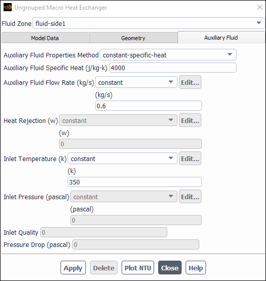
In the Auxiliary Fluid tab, specify the Auxiliary Fluid Properties Method, either as a constant-specific-heat or as a user-defined-enthalpy.
Auxiliary Fluid Flow Rate, Heat Rejection, Inlet Temperature, and Inlet Pressure can be provided as a constant, polynomial or piecewise-linear profile that is a function of time. If user-defined-enthalpy is selected as the Auxiliary Fluid Properties Method, you will need to specify the Inlet Quality and the Pressure Drop. More information is available in Specifying the Auxiliary Fluid Properties and Conditions.
Click in the Ungrouped Macro Heat Exchanger dialog box to save all the settings. Once you click the button, the NTU matrix will be computed from the raw data. Therefore, make sure you click at the very end of your setup.
Important: When you click , look for any error or warning message in the Ansys Fluent console. Some of the common errors you may see displayed are due to the NTU computations not converging. In such cases, check that
you have entered the data correctly
the values of the data are reasonable
the operating condition for the auxiliary fluid flow rate is not too far from the range of the heat transfer data
Other error messages you may encounter may be due to macros not getting any cells assigned to it. In such cases, make sure that
the heat exchanger core is rectangular
the directions are correct
you are using uniformly spaced cells in both directions
the mesh is either a hexahedra or wedge and is structured
Repeat steps (a)–(k) for any other heat exchanger fluid zones.
To use multiple fluid zones to define a single heat exchanger, or to connect the auxiliary fluid flow path among multiple heat exchangers, see Using the Grouped Macro Heat Exchanger Model.
For additional information, see the following sections:
- 16.5.3.2.1. Selecting the Zone for the Heat Exchanger
- 16.5.3.2.2. Specifying Heat Exchanger Performance Data
- 16.5.3.2.3. Specifying the Auxiliary Fluid Inlet and Pass-to-Pass Directions
- 16.5.3.2.4. Defining the Macros
- 16.5.3.2.5. Specifying the Auxiliary Fluid Properties and Conditions
- 16.5.3.2.6. Setting the Pressure-Drop Parameters and Effectiveness
Choose the fluid zone for which you want to define a heat exchanger in the Fluid Zone drop-down list.
Based on the heat transfer model you choose in the Model Data tab, some performance data must be entered for the heat exchanger.
ntu-model: For the ntu-model you will provide the heat transfer for different primary and auxiliary fluid flow rates. Click the button to open up a tabular dialog box. Set the number of auxiliary flow rates and primary fluid flow rates. The dialog box will resize itself accordingly. You will need to provide various primary fluid flow rates and auxiliary fluid flow rates and the corresponding heat transfer values. You may write this data to a file that can be read later.
simple-effectiveness-model: For this model, you will need to provide velocity versus effectiveness data. To provide this you can click the button. This will open up a tabular dialog box. In this dialog box, you can set the number of points in the curve, then you can provide velocities and corresponding effectiveness values (note that the effectiveness values must be within the range of 0–1). This data can be written to a file and read back.
To define the auxiliary fluid direction and flow path, you will specify direction vectors for the Auxiliary Fluid Inlet Direction and the Pass-to-Pass Direction in the Geometry tab. Figure 16.76: 1x4x3 Macros shows these directions relative to the macros.
For some problems in which the principal axes of the heat exchanger core are not aligned with the coordinate axes of the domain, you may not know the auxiliary fluid inlet and pass-to-pass direction vectors a priori. In such cases, you can use the plane tool as follows to help you to determine these direction vectors.
Drag the plane tool onto the boundary of the heat exchanger core. Refer to Plane Surfaces for additional information on plane surfaces and using the plane tool.
Translate and rotate the axes of the tool appropriately until they are aligned with the principal directions of the heat exchanger core. The depth direction is determined by the red axis, the height direction by the green axis, and the width direction by the blue axis.
Once the axes are aligned, click the button in the Ungrouped Macro Heat Exchanger dialog box. The directional vectors will be set automatically. (Note that the button will also set the height, width, and depth of the heat exchanger core.)
Open the Plane Surface Dialog Box to make the plane tool appear.
As discussed in The Macro Heat Exchanger Models, the fluid zone
representing the heat exchanger core is split into macros. Macros are
constructed based on the specified number of passes, the number of macro
rows per pass, the number of macro columns per pass, and the corresponding
auxiliary fluid inlet and pass-to-pass directions (see Figure 16.76: 1x4x3 Macros). Macros are numbered from
 to (
to ( ) in the direction of auxiliary fluid flow, where
 is the number of macros.
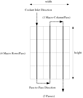
In the Ungrouped Macro Heat Exchanger dialog box, in the Geometry tab, specify the Number of Passes, the Number of Rows/Pass, and the Number of Columns/Pass. The model will automatically extrude the macros to the depth of the heat exchanger core. For each pass, the Number of Rows/Pass are defined in the direction of the auxiliary flow inlet direction and the Number of Columns/Pass are defined in the direction of the pass-to-pass direction.
Important: The Number of Rows/Pass, as well as the Number of Columns/Pass must be divisible by the number of cells in their respective directions. For example, if you have 50 cells in the auxiliary flow direction, you can use 25 for the Number of Rows/Pass, but you should not use 26 or 24. If you have 51 cells in that direction, you can only use 51 for the Number of Rows/Pass. The same holds true for the other direction.
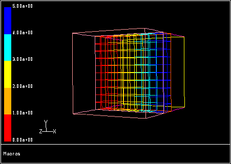
You can view the auxiliary fluid path by displaying the macros. To
view the macros for your specified Number of
Passes, Number of Rows/Pass, and
Number of Columns/Pass, click the
button at the bottom of the dialog box,
then click the button to display it.
To appropriately visualize the passes in the graphics window, you should
ensure Edges are visible from the Mesh Display Dialog Box, by selecting Draw
Mesh. The path of the auxiliary fluid is color-coded in
the display: macro  is red and macro
  is blue.
For some problems, especially complex geometries, you may want to include portions of the computational-domain mesh in your macros plot as spatial reference points. For example, you may want to show the location of an inlet and an outlet along with the macros. This is accomplished by enabling the Draw Mesh option. The Mesh Display Dialog Box will appear automatically when you enable the Draw Mesh option, where you can set the mesh display parameters. When you click the button in the Ungrouped Macro Heat Exchanger dialog box, the mesh display, as defined in the Mesh Display dialog box, will be included in the macros plot (see Figure 16.77: Mesh Display With Macros).
To define the auxiliary fluid properties and conditions, you will specify
the Auxiliary Fluid Flow Rate ( ) in the Auxiliary Fluid tab. The
properties of the auxiliary fluid can be specified using the
Auxiliary Fluid Properties Method drop-down list.
You can choose a constant-specific-heat
(
) in the Auxiliary Fluid tab. The
properties of the auxiliary fluid can be specified using the
Auxiliary Fluid Properties Method drop-down list.
You can choose a constant-specific-heat
( ) and set the value in the Auxiliary Fluid
Specific Heat field below, or as a user-defined function for
the enthalpy using the user-defined-enthalpy option and
selecting the corresponding UDF from the Auxiliary Fluid Enthalpy
UDF drop-down list.
) and set the value in the Auxiliary Fluid
Specific Heat field below, or as a user-defined function for
the enthalpy using the user-defined-enthalpy option and
selecting the corresponding UDF from the Auxiliary Fluid Enthalpy
UDF drop-down list.
The function should return a single value depending on the index:
Enthalpy for given values of temperature, pressure, and quality.
Temperature for given values of enthalpy and pressure
Specific heat for given values of temperature and pressure
The user-defined function should be of type
DEFINE_SOURCE(udf_name, cell_t c, Thread *t, real d[n], int index).
where n in the expression
d[n] would be 0 for
temperature, 1 for pressure, or
2 for quality. The variable
index is 0 for
enthalpy, 1 for temperature, or
2 for specific heat. This user-defined function
should return
real value; /* (temperature or enthalpy or Cp depending on index). */
If you want Ansys Fluent to compute the auxiliary fluid inlet temperature for a specified heat rejection, follow the steps below:
Enable the Fixed Heat Rejection option in the Model Data tab.
Specify the Heat Rejection (
 in Equation 6–15 in the Theory
Guide) in the Auxiliary
Fluid tab.
in Equation 6–15 in the Theory
Guide) in the Auxiliary
Fluid tab.Specify the Initial Temperature, which will be used by Ansys Fluent as an initial guess for the inlet temperature (
 in Equation 6–11 and Equation 6–13
in the Theory
Guide).
in Equation 6–11 and Equation 6–13
in the Theory
Guide).
If you want Ansys Fluent to compute the total heat rejection of the core for a given inlet auxiliary fluid temperature, follow the steps below:
Enable the Fixed Inlet Temperature option in the Model Data tab.
Specify the Inlet Temperature (
 in Equation 6–11 and Equation 6–13
in the Theory
Guide) in the Auxiliary
Fluid tab.
in Equation 6–11 and Equation 6–13
in the Theory
Guide) in the Auxiliary
Fluid tab.
If you enable the User Defined Enthalpy option under the Auxiliary Fluid Properties Method, you must also specify the Inlet Pressure (
 in Equation 6–21 in the Theory Guide) and
Inlet Quality (
in Equation 6–21 in the Theory Guide) and
Inlet Quality ( in Equation 6–20 in the Theory Guide).
The pressure drop parameters and effectiveness define the Core Porosity Model. If you would like Ansys Fluent to set the porosity of this a heat exchanger zone using a particular core model, you can select the appropriate model. This will automatically set the porous media inputs. There are three ways to specify the Core Porosity Model parameters:
Use the values in Ansys Fluent’s default model.
Define a new core porosity model with your own values.
Read a core porosity model from an external file.
If you do not choose a core porosity model, you will need to set the porosity parameters in the cell zone conditions dialog box for the heat exchanger zone(s). To do this, follow the procedures described in User Inputs for Porous Media.
The models you define will be saved in the case file.
Ansys Fluent provides a default model for a typical heat exchanger core. The default-model core porosity model is a list of constant values from the Ungrouped Macro Heat Exchanger dialog box. These constants are used for setting the porous media parameters. To use these values, simply retain the selection of default-model in the Core Porosity Model drop-down list in the Ungrouped Macro Heat Exchanger dialog box. (You can view the default parameters as described below.)
If you want to define pressure-drop and effectiveness parameters that are different from those in the default core porosity model, you can create a new model. The steps for creating a new model are as follows:
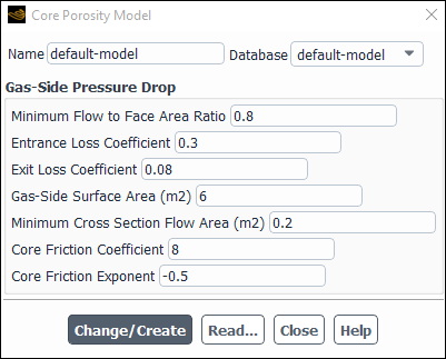
Click the button to the right of the Core Porosity Model drop-down list, for which default-model should have been selected. This will open the Core Porosity Model Dialog Box (Figure 16.78: The Core Porosity Model Dialog Box).
Enter the name of your new model in the Name box at the top of the dialog box.
Under Gas-Side Pressure Drop, specify the following parameters used in Equation 6–2 in the Theory Guide:
Minimum Flow to Face Area Ratio (
 )
)Entrance Loss Coefficient (
 )
)Exit Loss Coefficient (
 )
)Gas-Side Surface Area (
 )
)Minimum Cross Section Flow Area (
 )
)
and the Core Friction Coefficient and Core Friction Exponent (
 and
and  , respectively, in Equation 6–3 in the Theory
Guide).
, respectively, in Equation 6–3 in the Theory
Guide).Click the button. This will add your new model to the database.
You can read parameters for your Core Porosity Model from an external file. A sample file is shown below:
 ("modelname"
  (0.73 0.43 0.053 5.2 0.33 9.1 0.66))
The first entry in the file is the name of the model (for example,
modelname). The second set of numbers
contains the gas-side (primary-side) pressure drop parameters:
(


 )
)
To read an external heat exchanger file, you will follow these steps:
In the Core Porosity Model dialog box, click the button.
In the resulting Select File dialog box, specify the HXC Parameters File name and click . Ansys Fluent will read the core porosity model parameters, and add the new model to the database.
To view the parameters associated with a core porosity model that you have already defined, select the model name in the Database drop-down list (in the Core Porosity Model dialog box). The values for that model from the database will be displayed in the Core Porosity Model dialog box.
To define a single heat exchanger that uses multiple fluid zones, or to connect the auxiliary fluid flow path among multiple heat exchangers, you can use heat exchanger groups. To use heat exchanger groups, perform the following steps:
Read the mesh and make sure that the inlet and outlet for the heat exchanger are two separate zones.
Enable the calculation of energy in the Energy Dialog Box.
Setup →
Models → Energy
ON
Enable the Macro Model Group option and click the button in the Heat Exchanger Model Dialog Box to access the Macro Heat Exchanger Group dialog box.
Setup →
Models → Heat
Exchanger Edit...
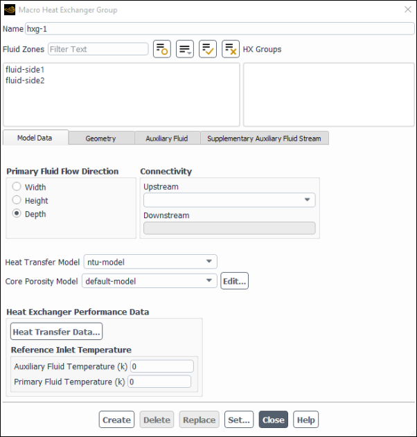
Specify the inputs to the heat exchanger group in the Macro Heat Exchanger Group dialog box (Figure 16.79: The Macro Heat Exchanger Group Dialog Box).
Enter the Name of the heat exchanger group.
Under Fluid Zones, select the fluid zones that you want to define in the heat exchanger group (Selecting the Fluid Zones for the Heat Exchanger Group).
Click the Model Data tab.
Under Primary Fluid Flow Direction, specify the primary fluid flow direction as either Width, Height, or Depth.
Under Connectivity, select the Upstream heat exchanger group if such a connection exists (see Selecting the Upstream Heat Exchanger Group).
In the Heat Transfer Model drop-down list, choose either the ntu-model or the simple-effectiveness-model. See step 3 in Choosing a Heat Exchanger Model for details about the differences between these two models.
From the Core Porosity Model drop-down list, specify the core model that should be used to calculate the porous media parameters for the zones in the group. More information is available in Setting the Pressure-Drop Parameters and Effectiveness.
If the ntu-model is chosen, a button will appear under Heat Exchanger Performance Data. Clicking the button will open the Heat Transfer Data Table Dialog Box, where you will enter experimental data that defines how heat transfer values relate to the fluid flow rates (Figure 16.67: The Heat Transfer Data Table Dialog Box). See Specifying Heat Exchanger Performance Data more details.
Enter the Auxiliary Fluid Temperature and the Primary Fluid Temperature for the ntu-model. These are the fixed inlet temperatures at which the test was performed to obtain the heat transfer data.
If the simple-effectiveness-model is chosen, then clicking the button, under the Heat Exchanger Performance Data, allows you to set the velocity and corresponding effectiveness for each point. More information is available in Specifying Heat Exchanger Performance Data.
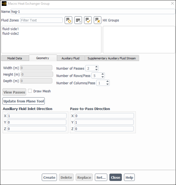
Click the Geometry tab (Figure 16.81: The Macro Heat Exchanger Group Dialog Box - Geometry Tab).
Define the heat exchanger macros by specifying the Number of Passes, the Number of Rows/Pass, and the Number of Columns/Pass. More information is available in Specifying the Auxiliary Fluid Inlet and Pass-to-Pass Directions and Defining the Macros.
Specify the Auxiliary Fluid Inlet Direction and Pass-to-Pass Direction (see Specifying the Auxiliary Fluid Inlet and Pass-to-Pass Directions).
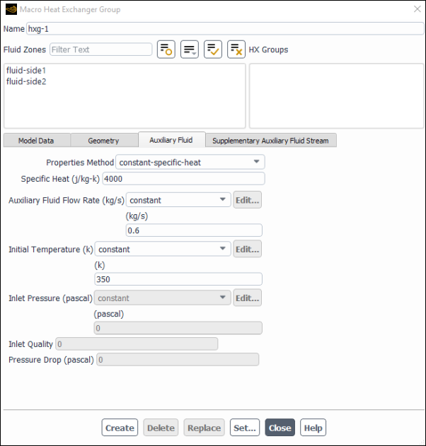
Click the Auxiliary Fluid tab (Figure 16.82: The Macro Heat Exchanger Group Dialog Box - Auxiliary Fluid Tab) to specify the auxiliary fluid operating conditions.
Specify the Specific Heat as either a constant-specific-heat or as a user-defined-enthalpy.
Auxiliary Fluid Flow Rate, Initial Temperature, and Inlet Pressure can be provided as a constant, polynomial or piecewise-linear profile that is a function of time (see Specifying the Auxiliary Fluid Properties and Conditions).
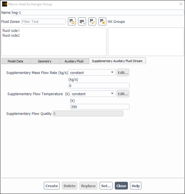
If a supplementary auxiliary stream is to be modeled, click the Supplementary Auxiliary Fluid Stream tab.
You can specify the Supplementary Mass Flow Rate as a constant, polynomial or piecewise-linear profile that is a function of time.
You can specify the Supplementary Flow Temperature as a constant, polynomial or piecewise-linear profile that is a function of time.
Click or in the Macro Heat Exchanger Group dialog box to save all the settings. changes the parameters of the already existing group that is selected in the HX Groups list.
Important: Creating or replacing any heat exchanger group initializes any previously calculated values for temperature and enthalpy for all macros.
If a heat exchanger group is composed of multiple fluid zones and you want to override any of the inputs defined in the previous steps, click the button to open the Ungrouped Macro Heat Exchanger dialog box (Figure 16.72: The Ungrouped Macro Heat Exchanger Dialog Box Displaying the Model Data Tab). Select the particular fluid zone as usual. Notice that the individual heat exchanger inherits the properties of the group by default. You may override any of the following:
Number of Passes, Number of Rows/Pass, and Number of Columns/Pass
Auxiliary Fluid Inlet Direction and the Pass-to-Pass Direction
Core Porosity Model
For additional information, see the following sections:
- 16.5.3.3.1. Selecting the Fluid Zones for the Heat Exchanger Group
- 16.5.3.3.2. Selecting the Upstream Heat Exchanger Group
- 16.5.3.3.3. Specifying the Auxiliary Fluid Inlet and Pass-to-Pass Directions
- 16.5.3.3.4. Specifying the Auxiliary Fluid Properties
- 16.5.3.3.5. Specifying Supplementary Auxiliary Fluid Streams
- 16.5.3.3.6. Initializing the Auxiliary Fluid Temperature
Select the fluid zones that you want to define in the heat exchanger group in the Fluid Zones drop-down list. The auxiliary fluid flow in all these zones will be in parallel. Note that one zone cannot be included in more than one heat exchanger group.
If you want to connect the current group in series with another group, choose the upstream heat exchanger group. Note that any group can have at most one upstream and one downstream group. Also, a group cannot be connected to itself. Select a heat exchanger group from the Upstream drop-down list under Connectivity in the Model Data tab of the Macro Heat Exchanger Group dialog box.
Important: Connecting to an upstream heat exchanger group can be done only while creating a heat exchanger group. The connection will persist even if the connection is later changed and the button is clicked. To change a connection to an upstream heat exchanger group, you need to delete the connecting group and create a new heat exchanger group with the proper connection.
The Auxiliary Fluid Inlet Direction and Pass-to-Pass Direction, in the Geometry tab can be specified as directed in Specifying the Auxiliary Fluid Inlet and Pass-to-Pass Directions in the Ungrouped Macro Heat Exchanger dialog box. Note that the Update from Plane Tool will set the height, width, and depth as the average of the fluid zones selected in the Fluid Zones.
The auxiliary fluid can be specified as having a constant-specific-heat, or a user-defined function can be written to calculate the enthalpy, as described in Specifying the Auxiliary Fluid Properties and Conditions.
The addition or removal of a supplementary auxiliary fluid is allowed in any of the heat exchanger groups. Note that auxiliary streams are not allowed for individual zones. You will specify the mass flow rate, temperature, and quality of the supplementary auxiliary fluid. You will also need to specify the heat transfer for various flow rates of primary and auxiliary flows. The auxiliary stream has the following assumptions:
The magnitude of a negative auxiliary stream must be less than the primary auxiliary fluid inlet flow rate of the heat exchanger group.
Added streams will be assumed to have the same fluid properties as the primary inlet auxiliary fluid.
When the heat exchanger group is connected to an upstream heat exchanger
group, Ansys Fluent will automatically set the initial guess for the
auxiliary fluid inlet temperature,  , to be equal to the
  of the upstream heat exchanger group. Thus the boundary
condition
of the upstream heat exchanger group. Thus the boundary
condition  for the first heat exchanger group in a connected series
will automatically propagate as an initial guess for every other heat
exchanger group in the series. However, when it is necessary to further
improve convergence properties, you will be allowed to override
for the first heat exchanger group in a connected series
will automatically propagate as an initial guess for every other heat
exchanger group in the series. However, when it is necessary to further
improve convergence properties, you will be allowed to override
 for any connected heat exchanger group by providing a
value in the Initial Temperature field. Whenever such
an override is supplied, Ansys Fluent will automatically propagate the new
for any connected heat exchanger group by providing a
value in the Initial Temperature field. Whenever such
an override is supplied, Ansys Fluent will automatically propagate the new
 to any heat exchanger groups further downstream in the
series. Similarly, every time the
to any heat exchanger groups further downstream in the
series. Similarly, every time the  boundary condition for the first heat exchanger group is
modified, Ansys Fluent will correspondingly update every downstream heat
exchanger group.
boundary condition for the first heat exchanger group is
modified, Ansys Fluent will correspondingly update every downstream heat
exchanger group.
If you want to impose a non-uniform initialization on the auxiliary fluid
temperature field, first connect the heat exchanger groups and then set
 for each heat exchanger group in streamwise order.
All heat exchangers included in a group must use the fixed  option. All heat exchangers within a heat exchanger group
must have the same
option. All heat exchangers within a heat exchanger group
must have the same  . In other words, no local override of this setting is
possible through the Ungrouped Macro Heat Exchanger
dialog box.
. In other words, no local override of this setting is
possible through the Ungrouped Macro Heat Exchanger
dialog box.
Postprocessing for the heat exchanger models involves computing the total heat rejection rate by setting up volume monitors and reporting of variables such as computed heat rejection, inlet or outlet temperature, specific heat, and mass flow rate.
Note that when postprocessing dual cell heat exchanger models using dialog boxes other than the Heat Exchanger Report dialog box (which requires you to explicitly specify whether you want reports on either the Primary or the Auxiliary fluid), attention must be paid to the fact that there are overlapping cell zones in the heat exchanger region. For example:
When creating an isosurface and making selections from the From Zones selection list of the Iso-Surface dialog box, you should never select both the primary and the auxiliary fluid zones at the same time. Note that if no selections are made in this list, then all the cell zones are selected.
When making selections from the Surfaces list of the Contours dialog box, you should not select a surface that is associated with the primary fluid zone and a surface associated with the auxiliary fluid zone at the same time, if those surfaces are spatially coincident.
For additional information, see the following sections:
Reporting the results for the heat exchanger models is done using the Heat Exchanger Report dialog box.
![]() Results → Reports
→ Heat Exchanger
Results → Reports
→ Heat Exchanger ![]() Edit...
Edit...
The following variable options are available for reporting:
Computed Heat Rejection
Inlet Temperature
Outlet Temperature
Mass Flow Rate
Specific Heat
To display the Computed Heat Rejection
Select Computed Heat Rejection from the Options list.
Select the Heat Exchanger from the selection list.
Click .
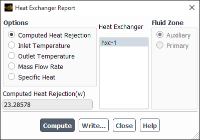
You can write the computed data to a file by clicking the button and entering the name of the heat exchanger report file in the Select File dialog box.
Inlet/Outlet Temperature can be reported for both primary and auxiliary fluid in the Heat Exchanger Report dialog box.
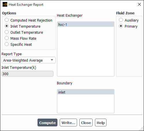
Select Inlet Temperature or Outlet Temperature from the Options list.
Select the heat exchanger from the Heat Exchanger selection list.
Select either Auxiliary or Primary as the Fluid Zone.
Select the appropriate boundary zone and report type from the Boundary and Report Type lists, respectively.
Important: Note that the macro heat exchangers (unlike the dual cell heat exchanger) do not contain an auxiliary cell zone. Hence, the Boundary and Report Type fields will not appear in the dialog box if you are reporting an auxiliary inlet/outlet temperature.
Click .
You can write the computed data to a file by clicking the button and entering the name of the heat exchanger report file in the Select File dialog box.
Mass Flow Rate can be reported for both the primary and auxiliary fluid in the Heat Exchanger Report dialog box.
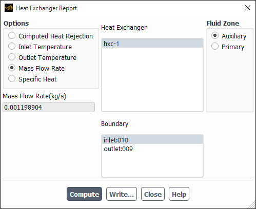
Select Mass Flow Rate from the Options group box.
Select the heat exchanger from the Heat Exchanger selection list.
Select either Auxiliary or Primary as the Fluid Zone.
Select the appropriate boundary zone and report type from the Boundary and Report Type lists, respectively.
Click .
Important: Note that the macro heat exchangers (unlike the dual cell heat exchanger) do not contain an auxiliary cell zone. Hence, the Boundary field will not appear in the dialog box if you are reporting an auxiliary fluid mass flow rate.
You can write the computed data to a file by clicking the button and entering the name of the heat exchanger report file in the Select File dialog box.
Specific Heat for the primary or auxiliary fluid can be reported through the Heat Exchanger Report dialog box. If specific heat is defined as a function of temperature, the specific heat reported will be a cell volume averaged value.
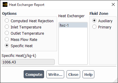
Select Specific Heat from the Options group box.
Select the heat exchanger from the Heat Exchanger selection list.
Select either Auxiliary or Primary as the Fluid Zone.
Click .
To postprocess the total heat rejection rate, you can set up a volume report definition to monitor convergence and view the computed values.
![]() Solution → Reports
→ Definitions →
New → Volume Report
→ Sum...
Solution → Reports
→ Definitions →
New → Volume Report
→ Sum...
Select Temperature and Heat Exchanger Source from the Field Variables drop-down lists.
Select the appropriate Cell Zones and click to close the Volume Monitor dialog box.
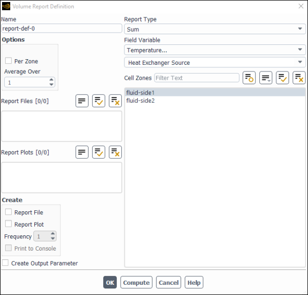
Important: Note that the macro heat exchangers contain only the primary fluid as the cell zone, but in case of the dual cell model, you can select either the primary or auxiliary fluid.
To report the results for the macro heat exchangers, you can use the following text command:
define →
models → heat-exchanger
→ macro-model →
heat-exchanger-macro-report
Specify the fluid zone  for which you want to obtain information.
To view the connectivity of the heat exchanger groups, use the text command:
(report-connectivity)