


This section contains information about generating a flux report. For more background information, see Fluxes Through Boundaries in the Theory Guide.
For additional information, see the following sections:
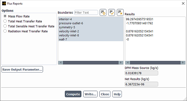
To obtain a report of mass flow rate, total heat transfer rate, or other fluxes on selected boundary zones, use the Flux Reports Dialog Box (Figure 41.23: The Flux Reports Dialog Box).
![]() Results → Reports
→ Fluxes
Results → Reports
→ Fluxes ![]() Edit...
Edit...
The steps for generating the report are as follows:
Specify which flux computation you are interested in by selecting one of the following under Options:
Mass Flow Rate
Total Heat Transfer Rate
In cases involving solar radiation, the heat flux associated with the Solar Load model is reported separately under Total Solar Source.
Total Sensible Heat Transfer Rate
Radiation Heat Transfer Rate
The net flux from volumetric radiation sources is reported in the Net Radiation Source field.
Pressure Work Rate
This reports the energy transfer due to pressure when a fluid zone undergoes normal zone motion relative to an adjacent solid zone. This pressure work is on the fluid side only, not on the solid side. This option is only available when the energy equation is enabled, the absolute velocity formulation is selected, and the Frame Motion and/or Mesh Motion option is enabled in the Fluid dialog box.
Viscous Work Rate
This reports the integral of the product of viscous stress with velocity over the external boundary of the domain with the boundary normal directed inside. Note that after reading case and data files into Ansys Fluent, the viscous work rate is zero. You need to run at least one iteration or time step to obtain the viscous work rate value. This option is available only when the energy equation is enabled and the pressure-based solver is selected.
Film Mass Flow Rate
This option is available only when the Eulerian Wall Film model is enabled—see Modeling Eulerian Wall Films.
Film Heat Transfer Rate
This option is available only when the Eulerian Wall Film model is enabled—see Modeling Eulerian Wall Films.
Electric Current Rate
This reports the total electric current through the selected boundaries. This option is available only if the potential equation is enabled—see Modeling Electric Potential Field and Electrochemistry Models.
In the Boundaries list, choose the boundary zone(s) on which you want to report fluxes.
You can use Filter Text entry box to filter the Boundaries list to show only the boundary zones that match the pattern you enter. For additional information on using the Filter Text entry box, see Filter Text Entry Boxes.
Note: Fluxes can only be computed on boundaries and not on user defined surfaces such as planes, points, iso-surfaces, and so on.
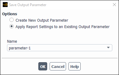
To create an output parameter for the reported value, click Save Output Parameter.... The Save Output Parameter Dialog Box (Figure 41.24: The Save Output Parameter Dialog Box) will open where you will specify the name of the newly created output parameter, or overwrite an existing output parameter of the same type. Ansys Fluent automatically creates generic default names for new input and output parameters (for example, parameter-1, parameter-2, and so on).
After the output parameter is created, it is listed in the Parameters Dialog Box, accessed via the Parameters... button in the Reports Task Page. You can create any number of output parameters of this report type.
Note: If you create an output parameter from a flux report and save the case and data (write), an equivalent report definition will be created when you read in the case file.
Click the Compute button to display the results of the selected flux computation for each selected boundary zone.
The Net Results field shows the summation of the individual zone flux results. If you specified the mass source terms in the Fluid dialog box, the integral mass flow rate value from the user-specified sources is reported in the User Source field and is added to the Net Results. Similarly, if you specified the energy source terms in the Fluid dialog box, the integral total heat transfer rate value from the user-specified sources is reported in the User Source field and is added to the net heat balance results reported in Net Results.
Important:
Additional steps must be taken prior to generating a flux report for an interior boundary zone that has the same fluid defined on either side. In such a case, the area vectors of the cell faces associated with the zone may have been automatically defined in an inconsistent manner when the mesh file was read into the solver. Since the flux for each individual cell face is calculated with respect to its area vector, such an inconsistency leads to inaccurate results when the face fluxes are summed to calculate the total flux of the boundary zone.
To ensure accurate flux results for such an interior zone, you must orient the area vectors by changing the definition of the zone Type to wall. You should then change the Type back to interior and proceed to generate the flux report.
Mass Flow Rate is calculated through the simulation domain or the specified zones. However, if you specify only the interior zone(s), the net mass flow rate may show as 0, because these internal boundaries are skipped when Ansys Fluent computes the net influx and outflux.
Note that the fluxes are reported exactly as computed by the solver. Therefore, they are inherently more accurate than those computed with the Flow Rate option in the Surface Integrals Dialog Box (described in Surface Integration).
Information on model-specific flux reports can be found in the sections that follow.
To report heat transfer for reacting flows, one of models in the Species Model Dialog Box must be enabled for the Total Sensible Heat Transfer Rate option to appear in the Flux Reports Dialog Box. For reacting flows, Ansys Fluent produces two kinds of reports that use a different treatment at the flow boundaries:
Total Heat Transfer Rate reports the total enthalpy flux, which consists of the thermal enthalpy, plus the species formation enthalpy when Volumetric Reactions are enabled. The heat rate based on this definition is a conserved quantity in reacting flows. See Heat Transfer Theory in the Theory Guide for details.
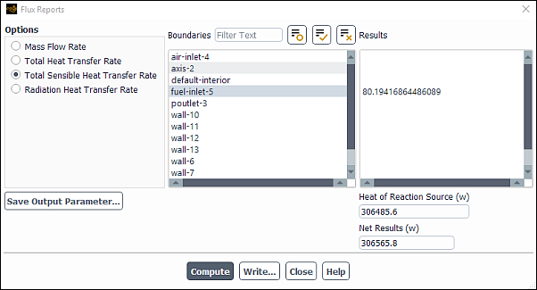
Total Sensible Heat Transfer Rate reports the total energy flux as defined in Equation 5–5 in the Theory Guide. Note that in reacting flows, this is not a conserved quantity and the addition or removal of heat due to the chemical reactions (Equation 5–11 in the Theory Guide) is reported separately in the Heat of Reaction Source field, as shown in Figure 41.25: The Flux Reports Dialog Box. If you have more than one reaction defined in your case, the Heat of Reaction Source reported is the sum of the heat for all reactions. For exothermic reactions the Heat of Reaction Source is reported as a positive quantity, while for endothermic reactions it will be a negative quantity.
Important: Note that both the Total Heat Transfer Rate and Total Sensible Heat Transfer Rate options report a Net Result, which may be used as an indication of the energy balance for the case. In general, and if heat sources other than the heat of reaction and DPM are not included in your problem, the Net Result reported in both the Total Heat Transfer Rate and Total Sensible Heat Transfer Rate options should be a small number for a converged calculation. However, if a reacting case is not well converged for both energy and species transport equations, the Net Result reported in the Total Heat Transfer Rate and Total Sensible Heat Transfer Rate options may differ. In that case, you may consider iterating further to achieve a fully converged solution. In addition, refer to the sections that follow for special considerations when including particles, multiphase models, or other volumetric energy sources.
Important: Note that for the non-premixed and partially premixed models the Heat of Reaction Source is calculated as the difference of the net Total Heat Transfer Rate and the net Total Sensible Heat Transfer Rate. The Heat of Reaction field function is not available for the non-premixed and partially-premixed models.
For the general procedure on generating flux reports, see Generating a Flux Report.
If you are using the discrete phase model (DPM), the contributions from the particle injections are reported separately and are included in the net mass and heat balance results. Consequently, the following quantities are included in the reports (see Figure 41.26: The Flux Reports Dialog Box with DPM):
Mass Flow Rate flux report: DPM Mass Source
Total Heat Transfer Rate flux report: DPM Enthalpy Source
Total Sensible Heat Transfer Rate flux report: DPM Sensible Enthalpy Source
For P1 or discrete ordinates (DO) radiation simulations, if Particle Radiation Interaction is selected in the Physical Models tab of the Discrete Phase Model dialog box, the Radiation Heat Transfer Rate reports the difference between the radiation emitted and the radiation absorbed on the surface of the particles in the DPM Radiation Source field.
Important: In the case of reacting flows with the DPM model, the Heat of Reaction Source entry reports the heat of all homogeneous reactions in the continuous phase, while the heat released or consumed due to particle reactions (for example, char combustion) is reported in the DPM Sensible Enthalpy Source field.
When you are using flux reporting with Lagrangian wall film particles, the total heat transfer rate reported as Net Results will equal the surface integral of the Wall Film Heat Flux field variable (in the Wall Film… category).
For the general procedure on generating flux reports, see Generating a Flux Report.
If you are using any of the multiphase models, the mass or heat rates can be reported separately for each phase and for the mixture phase depending on the model used. If you specified the mass source terms in the cell zone conditions dialog box for a specific phase, then the integral mass flow rate value from the user-specified sources is reported for the relevant phase in the User Source field and is added to the net mass balance results reported in Net Results. Similarly, if you specified the energy source terms in the cell zone conditions dialog box for a specific phase, the integral total heat transfer rate value from the user-specified sources is reported for the relevant phase in the User Source field and is added to the net heat balance results reported in Net Results.
Note that if your multiphase model includes mass or heat transfer processes between phases, the mass and heat transferred across the phases will be reported as an imbalance in the report of each phase. In order to check the overall balances for the multiphase cases you should select the mixture phase for your report. In that case, the report will include the sum of the fluxes and sources for all phases included in your model.
If you are solving a multiphase problem that includes chemical reactions, you should be aware of the following conventions when you are requesting a Total Sensible Heat Transfer Rate report:
If you select one of the phases with gas phase chemical reactions, the Heat of Reaction Source will only include contributions from reactions in the particular phase.
When you report the Total Sensible Heat Transfer Rate for the mixture phase, the Heat of Reaction Source entry will report the sum of the heat of reaction of all gas phase reactions in all phases plus the heat of any heterogeneous reactions that take place.
For the general procedure on generating flux reports, see Generating a Flux Report.
If you are using the DDPM, the mass and heat rates across the domain boundaries can be reported for each phase as described in Flux Reporting with Multiphase. In addition, for the discrete (DDPM) phase, the fluxes within the domain are also reported in the following fields of the Flux Reports dialog box and the Fluent console:
Mass Flow Rate flux report: DDPM In-domain Mass Rate
Total Heat Transfer Rate flux report: DDPM In-domain Heat Rate
These quantities report the total mass or heat rate contributions from:
particles that are released inside the domain (that is, do not enter the domain through the boundaries), and
particles that disappear inside the domain (that is, do not leave the domain through the boundaries).
Note that this is valid only for particles that are assigned to a discrete phase. The reported quantities extend the mass and heat rate balances of the standard reports that are available in multiphase simulations only for fluxes through domain boundaries.
The contribution from the DPM injections that have not been assigned to the discrete phase are reported as the DPM mass or enthalpy source, depending on your case. See Flux Reporting with Particles for details.
Figure 41.27: A Two-Phase Flow with Two Discrete Phase Injections shows an example of a steady state two-phase flow in a channel with one discrete phase and one fluid phase.
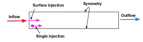
Two DPM injections, one surface injection at the inflow boundary and one single injection in the first cell layer adjacent to the inflow boundary, with the same mass flow rate are defined in the domain. Both injections are assigned to the discrete phase. All phases of the two-phase flow are leaving the domain through the outflow boundary.
When generating flux reports for the discrete phase, the mass flow rate for particles entering the domain via the surface injection is reported as a rate through the inlet boundary, while the mass flow rate for particles entering the domain via the single injection is reported as DDPM In-domain Mass Rate since the injection occurs within the domain as shown below in the mass flow rate report for the discrete phase. All particles leave the domain through the outlet. Since no mass is exchanged with the primary phase, the net value for the mass flow rate for discrete phase is nearly zero.
The mass flow rate report for the discrete phase is as follows:
                  particle-phase
                  Mass Flow Rate               [kg/s]
-------------------------------- --------------------
                           inlet              4.5e-05
                          outlet               -9e-05
        DDPM In-domain Mass Rate              4.5e-05
                ---------------- --------------------
                             Net        1.1922239e-14
The mass flow rate report for the primary phase is shown below:
                     fluid-phase
                  Mass Flow Rate               [kg/s]
-------------------------------- --------------------
                           inlet             5.55e-06
                          outlet             -5.1e-06
                 DPM Mass Source                    0
                ---------------- --------------------
                             Net              4.5e-07
The DPM Mass Source is reported as 0
because there are no injections in the domain that have not been assigned to the discrete
phase.
The balance for the mixture includes the mass flow rates from all the phases through the selected boundaries, the DPM Mass source from standard DPM injections, and the DDPM In-domain Mass Rate from the injections assigned to the discrete phase.
The mass flow rate report for the mixture is shown below:
                         mixture
                  Mass Flow Rate               [kg/s]
-------------------------------- --------------------
                           inlet            5.055e-05
                          outlet            -9.51e-05
                 DPM Mass Source                    0
        DDPM In-domain Mass Rate              4.5e-05
                ---------------- --------------------
                             Net        4.5000001e-07
For the general procedure on generating flux reports, see Generating a Flux Report.
Note: The following limitations currently exist for flux reporting capability with DDPM.
When reading a previously saved data file, the following steps are required to obtain the correct flux reports:
For steady-state simulations and transient simulations with the injection flow time spread over multiple time steps, you need to perform a single DPM iteration (steady-state cases) or a single time step (transient cases) to update information for the DDPM In-domain Mass Rate or DDPM In-domain Heat Rate.
Cases where injections both assigned and not assigned to a discrete phase are present in the domain must be rerun to obtain the correct values for the DPM mass or enthalpy source term.
Since the flux reporting with DDPM is purely a postprocessing functionality for the reporting of in- and outcoming fluxes for the DDPM phases and the mixture, it does not affect the simulation results. Any other postprocessing quantities can be reported as usual, and no additional steps are required.
If you have solved the potential equation, you can use the Flux Reports dialog box to compute the following quantities:
Electric Current Rate
You can report the total electric current through the selected boundaries.
Joule Heating Source
When you report Total Heat Transfer Rate for cases that involve the potential equation with the Include Joule Heating in Energy Equation option, the total Joule heating source in the domain is reported separately in the Joule Heat Source field. This value is also counted in the total heat balance calculation reported in the Net Results field.
For the general procedure on generating flux reports, see Generating a Flux Report.
The reported mass and heat balances address the flow that enters or leaves the domain through boundaries and the contributions from DPM sources and user-defined sources; they do not include the contributions from other volumetric sources, such as the heat exchanged in the Heat Exchanger Model. For this reason, a mass or heat imbalance may be reported. In that case, and in a converged calculation, the reported imbalance will be equal to that volumetric source.
For a Radiation Heat Transfer Rate flux report, the Net Radiation Source field provides the net flux from volumetric radiation sources and is computed as the difference between the emitted and absorbed volumetric radiation sources.
For the general procedure on generating flux reports, see Generating a Flux Report.