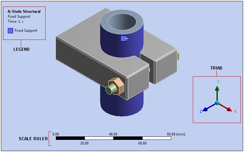
The Geometry window/tab displays a 3D graphical representation of your model. All view manipulation, geometry selection, and graphics display of a model occurs in this window.

The default components of the window, as illustrated above, include:
- Legend
The information presented by the Legend varies, but in general, it provides information about the currently selected object or objects as well as the analysis type, and includes annotations. For the above example, a Fixed Support object is selected. The face to which the support is applied is shown via color coding.
You can reposition the legend by dragging and dropping it to a location in the window.
- Scale Ruler
Based on the selected unit of measure, the ruler provides a reference for your geometry.
- Triad
Shows the global XYZ coordinate triad. The axes are color-coded as follows:
Red: X
Green: Y
Blue: Z
The Triad enables you to reorient the position of your model based on a desired axis as well as reset the isometric view (light blue ball). If you move your cursor around the triad, you will see an arrow appear that shows the direction that corresponds to the position of your cursor (+x, -x, +y, -y, +z, -z). If you click the arrow, it changes your view so that the axis indicated by the arrow is facing outward.
You can turn these options on and off using selections Show drop-down menu on the Display group on the Display tab.
Full Screen Mode
Mechanical offers a full screen mode so that you can view and/or present the results of your analysis by maximizing the Geometry window and hiding all other interface elements (by default). You activate full screen mode by selecting the Full Screen option from the Layout group on the Home tab. Or, you can use the F11 key when the Geometry window, the tree Outline, or the Details view have focus. The tab option and the F11 key toggle the display on and/or off. Also note that you can use Key Assignments from when the Full Screen active to displays other interface panes, such as the Outline, if desired.
Contextual Menu Options
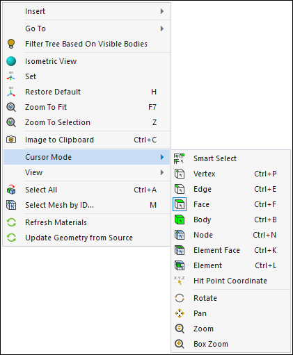
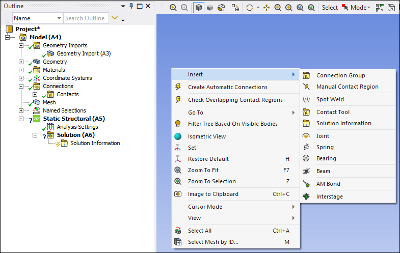
Right-clicking the mouse in the Geometry window provides a context menu with a variety of options. The common menu options and specifically, the Cursor Mode menu, are illustrated below. Furthermore, the menu displays additional options that are based on the object you have selected. For example, the Insert and Go To options shown below are often available and their menu selections depend upon the tree object that is selected.

- Insert
The options of the menu depend upon the object selected in the tree. For example, with the Connections object selected, right-click in the geometry window and then select to display the menu of connection options illustrated below.

Tip: The Objects Reference section provides descriptions for all objects and their context menu options.
- Go To
The options of the menu depend upon the object selected in the tree. For example, with a geometric entity selected on the model, right-click in the geometry window and then select to display the menu of options illustrated below. See the Correlating Tree Outline Objects with Model Characteristics section for more information.

- Filter Tree Based on Visible Bodies
Filters the tree so that only visible bodies and objects associated with any visible body display.
- Isometric View
Displays your model in the default isometric view.
- Set
This option enables you can define a custom isometric viewpoint based on the current viewpoint. That is, you position your model where you would like it, using the other view options as desired, and then selecting this option establishes a new .
- Restore Default
This option resets the to the application default.
- Zoom To Fit
Fits the entire model in the Geometry window.
- Zoom To Selection
Zoom in on the currently selected item (geometry/mesh/etc.) in the Geometry window.
- Image to Clipboard (Ctrl+C)
For the Windows platform, this option performs a snapshot of whatever is currently displayed in the Geometry window and copies it to the clipboard so that you can paste it into compatible applications.
- Cursor Mode
This option provides a different method for selecting the cursor mode. See the Graphics Toolbar section of the Help for a description of each selection.
- View
This option changes the viewpoint of your model. It operates much like the Triad.
- Select All
Selects all items in the Model of the current selection filter type (vertex, edge, face, or body).
- Select Mesh by ID (M)
This option enables you to select mesh nodes or elements using their ID. This feature can be activated with the M key when the Geometry window is active. And, it also provides an option to create Named Selections for your selections.
- Reset Body Colors
Reset the body colors back to the default color scheme.
Note: As applicable and based on the object that you have selected in the tree, the contextual menu also provides options specific to that object.
Discrete Legends in the Mechanical Application
The following additional legends are available based on the object you have selected in the application.
Geometry Legend : Content is driven by Display Style selection in the Details view panel.
Joint Legend : Depicts the free degrees of freedom characteristic of the type of joint.
Results Legend : Content is accessible via the right mouse when the legend for a solved object in the Solution folder is selected.
Displaying Shells for Large Deflections
The display of shells may become distorted for large deformations such as in large
deflection, explicit dynamics analyses, etc. A workaround is to disable shell thickness by
toggling option in the Style group of the
Display tab. Or, set a Workbench variable,
UsePseudoShellDisp = 1, via the
. It may be necessary to toggle the deformation scaling from True Scale
to Undeformed to True Scale again. Note that this
option requires True Scaling to work properly.


