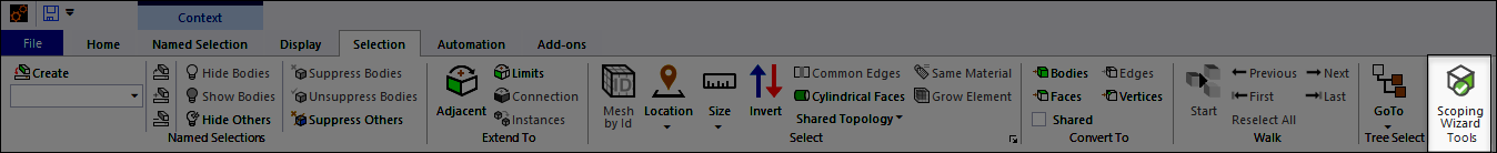
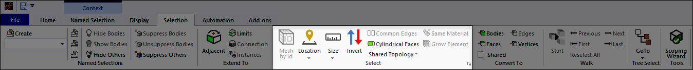
The Selection tab facilitates the selection of geometric and/or mesh entities either through graphical picking or through some criterion-based selection feature, such as size or location.
Note: The tab's functionality uses Ansys ACT. The relevant python modules (selection.py and toolbar.py) are available for review in the install folder: aisol/DesignSpace/DSPages/Python.
This tab contains the following Groups.
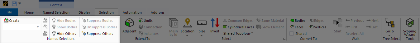
Named Selections
The Named Selections group enables you to select, add to, and remove items from existing user-defined named selections as well as modify visibility and suppression states. See the Applying Named Selections via the Ribbon section for detailed description of the options.
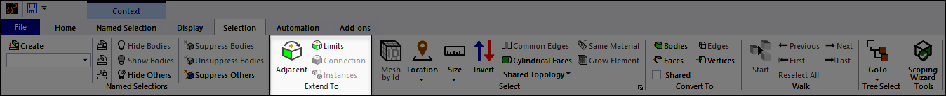
Extend To
The Extend To group enables you to add adjacent faces or edges, within angle tolerance, to the currently selected face or edge set, or adds tangent faces or edges within angle tolerance, to the currently selected face or edge set. See the Extend To topic for additional information about these options.
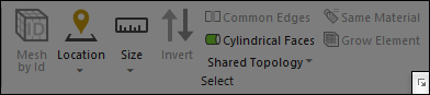
Select
The Select group provides options for making and/or manipulating geometry selections.
Options for this group include:
| Option | Description |
|---|---|
| Mesh by Id | Opens a dialog that enables you to select mesh nodes and mesh elements using their IDs once you have generated the mesh for your model. This feature is modeless and therefore enables you to work with the user interface while the dialog box is displayed. This feature is also available from the context (right-click) menu, , in the Geometry window. You can also activate the feature using the M key, when the Geometry window has focus. See the Selecting Nodes and Elements by ID section for more information. |
| Location Note: For a line body geometry, the location is estimated as the weighted arithmetic mean of the centroids of its edges. The weight is based on the edge lengths. | Displays a drop-down menu of the following options:
|
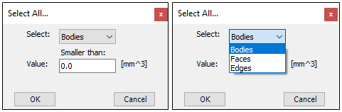
| Size | Displays a drop-down menu of the following options:
Note: These options are also available from the Select By > menu on the Graphics Toolbar. |
| Selects all entities (face, edge, etc.) that are not currently selected. The option only selects entities of the same type. For example, if you have a face selected and select Invert, the application selects all the faces on your model except the face that you had selected. | |
| Selects common edges of selected faces. | |
| Selects all faces on the model that are cylindrical (they do not need to be full cylinders). | |
| Displays a drop-down menu of options, including, and . These options select any edge or face on the interior of a multi-body part. | |
| Selects all bodies with the same Material Assignment as the currently selected body. | |
| Selects all elements adjacent to your current element selection. This option effectively grows the element selection by one layer of elements. | |
| Set Tolerances |
 Opens a dialog box that enables you to specify a search tolerance for your geometric entity selections. The dialog fields include Zero Tolerance and Relative Tolerance. Note: Tolerance settings are only applicable when using the option or a Location option (see above). 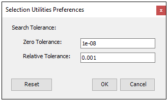 By default, the Zero Tolerance property is set to
|
Convert To
The Covert To group enables you to change (convert) your currently selected geometric entity or mesh item to a different geometric entity or mesh item.
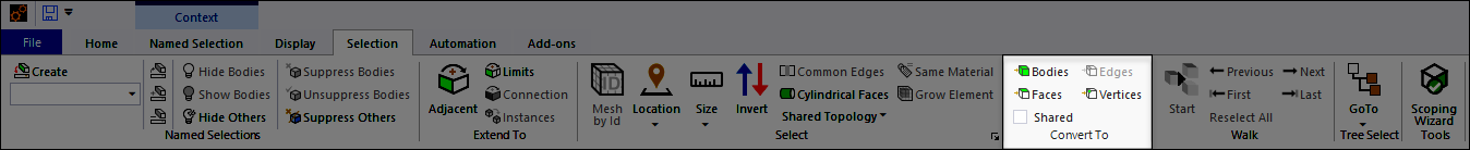
This group includes the following options:
| Option | Description |
|---|---|
| Selects only geometric entities that are shared by all currently selected entities. | |
| Selects all bodies associated with your current selection of either faces, edges, vertices, elements, or nodes. The selection mode automatically changes to Body selection. | |
| Selects all Faces associated with your current selection of either bodies, edges, vertices, elements, or nodes. For example, if your selection is a body or bodies, all faces on that body will be selected. The selection mode automatically changes to Face selection. | |
| Selects all Edges associated with your current selection of bodies, faces, vertices, elements, or nodes. For example, if vertices are selected, any edges associated with the vertices will be selected. The selection mode automatically changes to Edge selection. | |
| Selects all Vertices associated with your current selection of either bodies, faces, edges, elements, or nodes. The selection mode automatically changes to Vertex selection. |
Note: These options, except for the Shared option, are also available from the Convert menu on the Graphics Toolbar.
Walk
The Walk group enables you to highlight and zoom in on entities of your model. Once you select more than one geometric or mesh entity (using Graphics Toolbar options) from the Geometry window and select the Start option, the application automatically highlights and zooms in on each entity in turn as you use the navigation options. The feature supports all geometric and mesh (mesh generation required) selections, including Body, Face, Edge, Vertex, Node, Element Face, and Element.
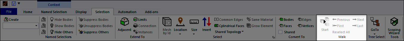
Once you have made selections and selected the Start option, the application caches each selected entity into memory. You then use the navigation options (Previous/Next/First/Last) to step through your selections. The cached selections are maintained until you make new selections and click the Start option.
Tip: When the Geometry window has focus, the (or [Ctrl]+[A]) context (right-click) menu option can be useful when using this feature.
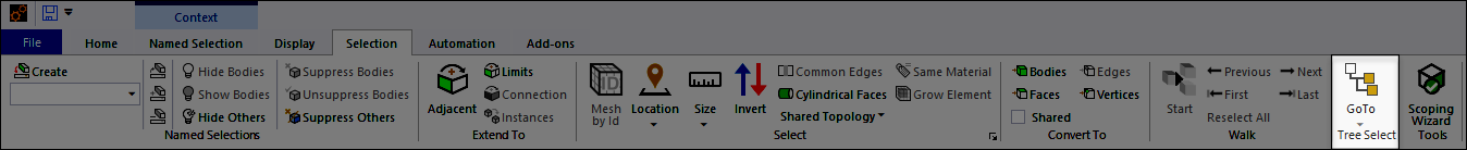
Tree Select
This group provides a drop-down menu of Go To options. These options correlate model selections to tree objects. Selecting an option highlights a tree object. See the Correlating Tree Outline Objects with Model Characteristics section for more information. The options are also available from the context (right-click) menu of the Geometry window.
Tools
The Tools group contains the Scoping Wizard option. This option displays the Scoping Wizard pane. This feature enables you to reidentify an object’s scoping lost because of a geometry update. Once identified, you can use the options of the feature to reestablish the original scoping.