The status bar provides information about your simulation.
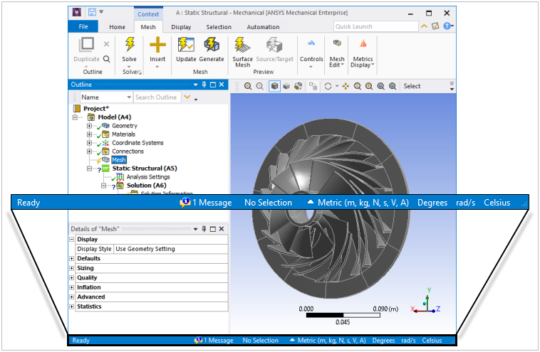
Illustrated here, the status bar displays information panes. Generally, when information is available, you can single-click a pane to display an associated menu or window.

Go to a status bar component topic for more information about its purpose:
Progress Pane
This area of the status bar displays the progress of certain application processes, such as mesh generation and solution processing.
Progress Bar (Interrupt and Stop Options)
During an active process, the application displays a progress bar in the progress pane. And, depending on the process, it also provides an Interrupt (pause icon) option and/or Stop (red square icon) option. An example of the progress of a solution is illustrated blow. It includes both the Interrupt and Stop options.

Limitation: You may observe that the progress bar becomes hidden when you run simultaneous processes that use the feature. Such as animating a result while another analysis included in the project is solving. You can address this behavior by setting the Hide Progress Window preference to (Options > UI Options > Progress).
Progress Tool Tips (via Mouse Over)
During an active process, if you hover your mouse over the progress bar, a button, or the description (percentage, etc.) of the progress and process, a tool tip displays. An example of a mesh generation process is shown below.
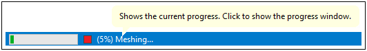
Note that a single-click in the progress pane opens an associated progress window (shown here). This window is the legacy progress display for Mechanical.
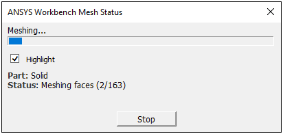
Note: Using the UI Options preference setting Hide Progress Window, you can choose to always display progress windows.
Tooltip Display
When you hover your mouse over an interface option, a tooltip displays in the bottom right corner of the bar. Here is an example of the tooltip for a mouse-over of the Solve button.

Application Messages
The status bar contains a pane that displays whether there are application generated messages (errors, warnings, and/or information). A single-click the pane to display the Message window.

Selection Information
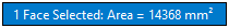
The Selection Information pane displays information about the currently selected geometric entity or entities. Such as area, length, or location. In the following example, the area of a single face is displayed.
A single-click the pane displays the Selection Information window.
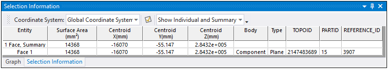
Example Selection Information includes (but is not limited to):
A selected node or element number if only one node/element is selected.
The location of a node or vertex if one is selected.
The combined volume of selected bodies, area of selected faces, and lengths of edges.
The radius of a single circular edge or face that is selected.
Angle between three nodes (always in degrees).
The angle between two planar surfaces (always in degrees).
The angle between two straight edges (always in degrees).
Note:
If there is no associated information, the Selection Information pane indicates No Selection.
Geometry calculations such as length and area are an approximation based on geometry information contained in either the CAD data or graphics tessellation.
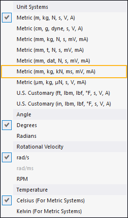
Units of Measure Pane
This pane displays the currently selected Unit systems. Selecting this pane displays the Units menu enabling you to change the current unit system.
License Read-Only Display
If a license is not available when you open Mechanical, the application automatically opens in Read-Only Configuration mode as illustrated below. Once a license becomes available and you activate it, the application automatically exits this read-only mode.

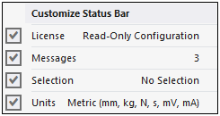
Customize the Status Bar
When you right-click the status bar, the following menu displays. Using this menu, you can select whether to hide (or show) certain status bar options.