


Defines connections among selected bodies. Includes global settings in Details pane that apply to all Contact Region or Joint child objects.
 |
Object Properties
The Details Pane properties for this object include the following.
| Category | Properties/Options/Descriptions |
|---|---|
|
Definition | |
|
Scope |
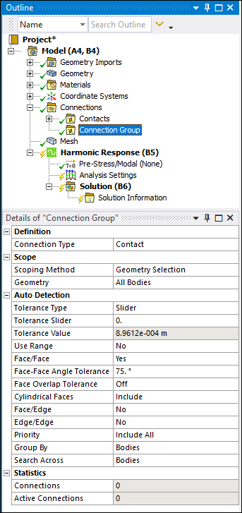
Scoping Method Geometry: Displays when the Scoping Method is set to Geometry Selection. In this case, use selection filters to pick geometry, click in the Geometry field, then click Apply. Named Selection: Displays when the Scoping Method is set to Named Selection. Source Assembly: Displays when the Scoping Method is set to Source Assembly (Only applicable for Assembled External and Mechanical Models). |
|
Face/Face Angle Tolerance: Visible when the Face/Face property is set to . When working with Face/Face automatic contact detection, this property enables you to define the minimum angle between two face normals. This minimum angle is the threshold below which the application will ignore the faces from proximity detection. The default value is 75°, the minimum value is 0°, and the maximum value is 90° (perpendicular).Face Overlap Tolerance: Appears only for contact groups when Face/Face is set to Yes. Cylindrical Faces (3D Only): Only visible when the Connection Type property is set to and the Face/Face property is set to . Options include:
Face/Edge: Only displays for contact groups. Edge Overlap Tolerance: Only displays for contact groups when Face/Edge is set to Yes, Only Solid Body Edges, or Only Surface Body Edges. Edge/Edge: Only displays for contact groups. Priority: Only displays for contact groups. Revolute Joints: Only displays for joint groups. Fixed Joints: Only displays for joint groups. | |
|
Statistics |
Connections: Displays the number of connections associated with this parent object. Active Connections: Displays the number of connections that are currently active for this parent object (that is, not Suppressed). |
Tree Dependencies
Valid Parent Tree Object: Connections.
Valid Child Tree Objects: Comment, Contact Region, Figure, Image, and Joint.
Insertion Methods
Use any of the following methods after highlighting Connections object:
Click on the Connections Context Tab.
Right-click the Connections object (or on another Connection Group object), or in the Geometry window; then .
Insert a Contact Region or Joint object. A separate parent Connection Group object is created automatically for each of these two types of objects, and is renamed Contacts or Joints accordingly.
Right-click Options
In addition to common right-click options, relevant right-click options for this object include:
API Reference
See the Connection Group section of the ACT API Reference Guide for specific scripting information.