


This section examines several common actions you can take when working with connections. Go to a desired topic:
Automatically Generate Connections
You can automatically generate supported connections for a group of bodies in a model and use a separate tolerance value for that group. The supported connection types are Contact Region and Joint.
To automatically generate connections for a group of bodies:
Insert a Connection Group group folder under the Connections folder by selecting the Connection Group option on the Connections Context tab or by selecting > Connection Group from the context menu (right mouse click) for this folder.
From the Details view of the Connection Group object, select the desired Connection Type. The default is Contact.
Select some bodies in the model based on the Scoping Method. The default is Geometry Selection scoped to All Bodies.
If applicable, set the Auto Detection properties. Note that these properties will be applied only to scoped geometries for this connection group.
Choose from the context menu (right mouse click) for the Connection Group.
Note: For small models, the auto contact detection process runs so fast that the Contact Detection Status (progress bar) dialog box does not get displayed. However, for large models with many possible contact pairs, the progress bar dialog box is displayed showing the contact detection progress. If you click the button on the dialog box while contact detection is processing, the detection process stops. Any contact pairs found by that moment are discarded and no new contacts are added to the tree.
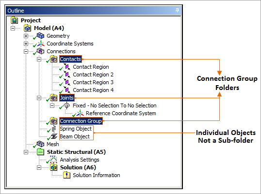
The resulting connection objects will be placed under this folder and the folder name will be changed from its default name Connection Group to a name based on the connection type. The folder name for contacts will be Contacts and for joints it will be Joints. Once the Connection Group folder contains a child object, the Connection Type property cannot be changed. Each Connection Group folder will hold objects of the same type and will include a worksheet that displays only content pertaining to that folder. When two or more Connection Group folders are selected and you choose , auto detection for the selected Connection Group folders will be performed. The option is also available from the context menu (right mouse click) for the Connections folder provided there is at least one Connection Group folder present. When you choose this command from the Connections folder, auto detection will be performed for all connection groups under this folder.
Manually Inserting Connection Objects
You can insert any supported connection objects manually using Context tab options or using the context (right-click) menu on the Connections or Connection Group folder. When inserting a connection object from the Connections folder, a Connection Group object will automatically be created in addition to the connection object itself. When inserting a connection object from a Connection Group folder, if it is an empty folder, any supported type of object can be inserted. However, if the folder already contains at least one object, only objects of the same type can be inserted.
Checking for Overlapping Contact Regions
Overlapping contact conditions arise when a face or edge is contained in more than one Contact Region. Mechanical supports this situation for the Mechanical APDL solver; however, if your analysis is incorporated into a fluid analysis, issues can arise.
Mechanical provides the context menu option Check Overlapping Contact Regions to identify any overlapping contact regions in your model so that you can address them appropriately.
Setting Default APDL Names
The context (right-click) menu option for the Contact Region object, , enables you generate system default names for the Contact/Target APDL Name properties. These properties are optional and only available for the Mechanical APDL solver. See the Setting Default APDL Names section for more information.
Searching for Duplicate Pairs
Generating connections (Contacts or Joints) and Mesh Connections, either automatically or manually, may result in the same geometry pair being scoped by more than one connection object. This may over constrain the model which may lead to convergence difficulty problems in the solver. If this situation occurs, use the context (right-click) menu option , to check connection objects for duplicate pairs. You can then modify or the geometry scoping of the duplicated pairs or delete the duplicate connection objects.
Note: The application considers connection objects whose scoping has been flipped when searching for duplicate pairs. For example, if you have two Contact Regions that are scoped to the same geometry pair but have reversed Contact and Target settings, these regions are considered a duplicate pair.
When one or more duplicate pairs are found in the existing connection objects (which includes Mesh Connections), the application displays the following warning message in the Messages window for a connection object that shares the same geometry pair.
"This connection object shares the same geometries with one or more connection objects. This may over-constrain the model. Consider eliminating some connection objects."
To search for connection objects that share the same geometry pair with more than one connection object, select multiple connection objects before selecting . Or you may issue the search from a Connections/Connection Group or Mesh Connections/Mesh Connection Group folder, the application searches all connection objects under this folders for duplicate pairs.
Once the application detects duplicates, right-click the message in the Messages window and select from the context menu. The application highlights the associated connection object in the tree. To find other connection objects that share the same geometry pair, right-click the highlighted object and select from the context menu; all connection objects that share the same geometry pair will be highlighted in the tree.
Moving and Copying Connection Objects
To move a connection object to another folder of the same connection type, drag the object and drop it on that folder. For example, to move a contact region object, drag the object from its current Contacts folder and drop it on another folder whose Connection Type is Contact (possibly named Contacts 2).
To copy a connection object to another folder of the same connection type, hold the Ctrl key while performing the move procedure described above.
Creating Contact Sizing Controls for Contact Regions Automatically
You can create contact sizing controls automatically by:
Dragging and dropping the Contacts folder onto the Mesh object to create a Contact Sizing control for each contact region in the folder.
Selecting the Contacts folder or an individual Contact Region in the Tree and using the RMB option Create > Contact Sizing to create Contact Sizing controls for the selected contact regions.
Treatment of Legacy Databases
Supported connection objects from databases of previous versions of Ansys Workbench will be grouped based on their types and migrated into Connection Group folders.
Contacts from legacy databases are resumed with the property set to .