


Contact regions are said to be “overlapping” when the same entity (face or edge) is a member of more than one contact region or when multiple contact regions share the same geometry. When you export a mesh to Ansys Fluent or Ansys CFX, contact regions become mesh interfaces and interfaces must be unique. That is, if there are overlapping contact regions, the overlaps need to be resolved into exclusive groups for the export to be successful.
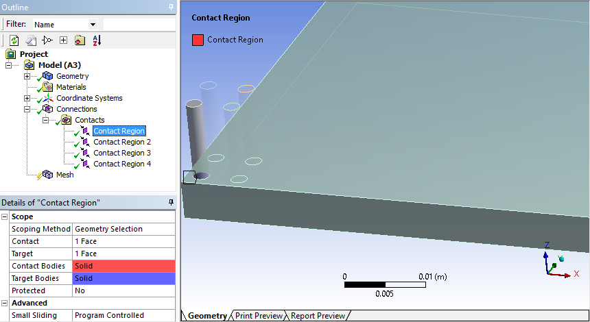
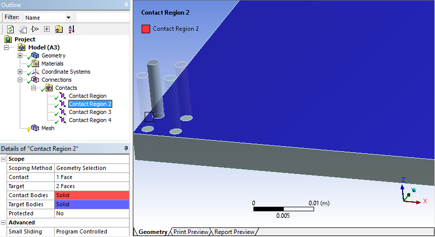
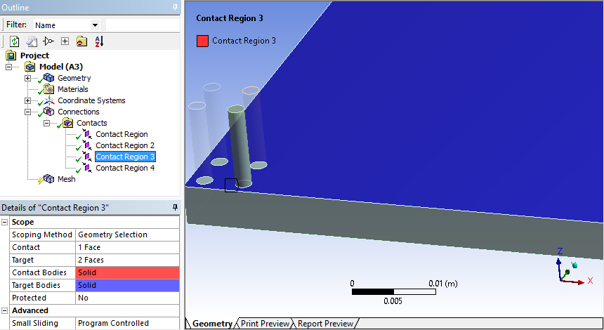
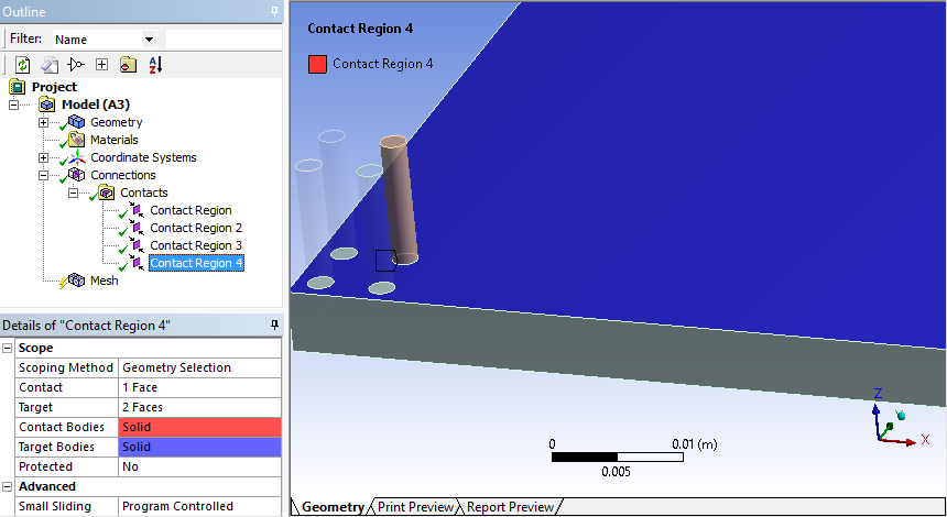
Overlapping entities can be from a variety of sources. In the examples shown in the following series of images, the first contact region has one face as a contact and one as a target, this is a good connection for Ansys Fluent or Ansys CFX. The other three contact regions have two faces as targets and only one face as a contact, the extra target face in each of these contact regions overlaps. Hence, results in overlapping contact regions that may need to be addressed for the export to succeed. In this particular case, the default tolerance that was used to detect contacts was too large. This problem could be fixed by deleting all the contacts and using a smaller Face Overlap Tolerance to recreate them.
Other cases of overlap may have different causes and solutions. To identify overlapping contact regions so that you can resolve them and export the mesh successfully, follow these steps:
Right-click the Connections, Connection Group, or Contacts folder in the Tree and choose Check Overlapping Contact Regions.
If any overlapping contact regions are found, an informational message appears in the Messages window.
Right-click the message and select Go To Object.
The overlapping contact regions that are responsible for the message are highlighted in the Tree.
With all of the overlapping contact regions still highlighted in the Tree, right-click one of them and select Group.
All of the overlapping contact regions are grouped into a new folder to isolate them for diagnosis.
To resolve the overlapping contact regions, select each contact region that was placed into the new folder one at a time and examine its properties. Verify that all associated properties are defined appropriately. The following approaches are recommended:
Often tolerances are set too large, as described in the example shown above. Try deleting all the contacts and using smaller tolerance values to recreate them. It may help to set Tolerance Type to Value rather than Slider, so that you can enter an exact Tolerance Value. Make sure the Tolerance Value and Face Overlap Tolerance are set to reasonable values before regenerating the contacts.
Depending on the case, setting Group By to Faces may help to pinpoint problematic faces. In other situations, setting Group By to Bodies and promoting the overlapping contact regions to Named Selections may be a better approach.
If the tolerances are different for different bodies, run contact on selected bodies with different tolerances.
If the faceting of the geometry is too coarse, increase the facet tolerance in DesignModeler.
If some of the overlapping contact regions are not needed in Ansys Fluent or Ansys CFX, you can suppress them so they will not affect the success of the export.
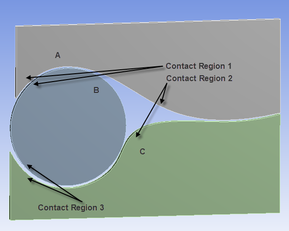
If the case involves cyclic constraints, use imprinting in DesignModeler or SpaceClaim. Imprinting results in exact pairs and ensures faces have common boundaries between parts. Refer to Figure 29: Geometry with Cyclic Redundancies, which illustrates a complex case of cyclic redundancy. Here the overlap is A->B->C->A, where A is the face contact of the top body, B is the cylindrical face of the middle body, and C is the face in contact of the bottom body.
After you have resolved all of the overlapping contact regions, you can retry the export.
Note: This feature is applicable to part-based meshing only.