After reading the boundary mesh and performing the necessary modifications (such as merging duplicate nodes, edge swapping) you will create the volume mesh.
Depending on the type of mesh you are starting from (boundary mesh only, boundary mesh with hexahedral cells in one or more regions, and so on), you can automatically generate the mesh, manually generate the mesh step by step, or use a combination of manual and automatic commands.
You can create several types of meshes comprising different element types. The meshing strategy and the use of the Auto Mesh tool are described in this chapter. Information on how to deal with thin regions, quad-tet transition elements (pyramid and non-conformal meshing), and creation of a heat exchanger zone are also described. Detailed descriptions of meshing techniques such as prism meshing, tetrahedral and hexcore meshing options, and so on are described in subsequent chapters.
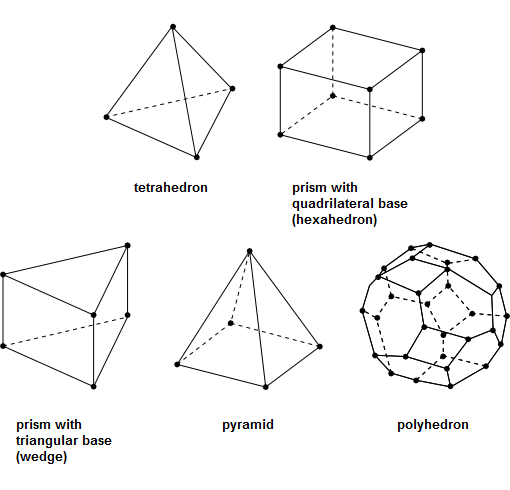
You can use a variety of cell shapes to mesh the domain:
A mesh consisting entirely of tetrahedral elements is a tetrahedral mesh, and a mesh with any combination of cell shapes is referred to as a hybrid mesh.
Before generating a volume mesh, determine the shapes that are appropriate for the case you are solving, then follow the instructions for creating the required cell types. Most cases will fall into one of the following categories:
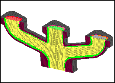
If you require a high mesh resolution in some portion of the domain, such as a boundary layer, you can obtain an efficient and better quality mesh by meshing that portion with prisms (wedges) and then meshing the rest of the domain with tetrahedra (tets). The resulting mesh is referred to as a viscous hybrid mesh.
The procedure is as follows:
Build one or more layers of prisms, starting from the appropriate boundary (or boundaries). Refer to Generating Prisms for details.
Create a domain encompassing the region to be meshed with tetrahedra. Refer to Using Domains to Group and Mesh Boundary Faces for details.
Generate the tets in the selected domain using either an automatic tet mesh generation, a manual tet mesh generation, or a combination of the two. Refer to Generating Tetrahedral Meshes for details.
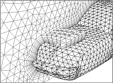
Figure 7.67: Mesh with Prisms in a Boundary Layer Region shows several layers of prisms in a portion of a mesh created in this manner. The prisms extend throughout the entire region bounded by the quadrilateral faces, but only a few of them are shown here.
The surface mesh originally contained only triangular faces. The quadrilateral faces are created automatically when the prisms are built on the triangular faces.
If the quadrilateral faces of the prisms do not lie on the external boundary of the domain (that is, if the prism region begins and/or ends in the interior of the domain), create a layer of transitional pyramids between steps 1 and 2. Refer to Generating Pyramids for details.
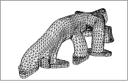
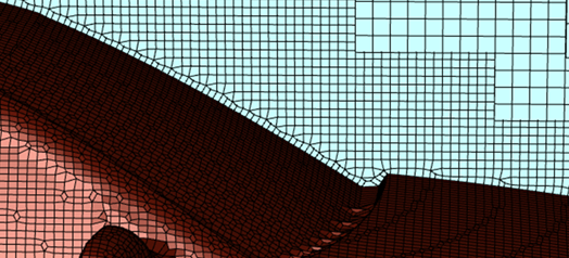
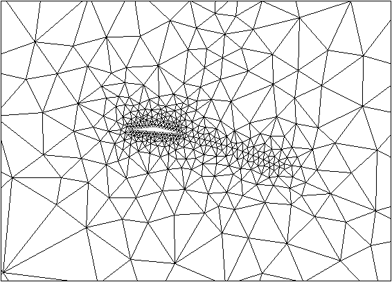
If you have no special boundary layer resolution requirements, you can generate a mesh consisting entirely of tetrahedra (see Figure 7.68: Surface Mesh Containing Only Tetrahedra). You can use the automatic tetrahedral mesh generation procedure, the manual procedure, or a combination of both. Refer to Generating Tetrahedral Meshes for details.
Start from a boundary mesh that contains triangular and quadrilateral faces as well as hexahedral cells in the quadrilateral face regions. The resulting mesh is referred to as a zonal hybrid mesh.
Add a layer of pyramids to the quadrilateral boundary face zone that lies between the hexahedral region and the adjacent region to be meshed with tetrahedra. This creates the triangular boundary face zone that is required to create tetrahedra in the adjacent region. Refer to Generating Pyramids for details.
Create a domain encompassing the region to be meshed with tetrahedra. Refer to Using Domains to Group and Mesh Boundary Faces for details.
Generate the tetrahedra in the selected domain using either automatic or manual tet mesh generation, or a combination of both. Refer to Generating Tetrahedral Meshes for details.
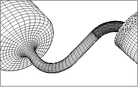
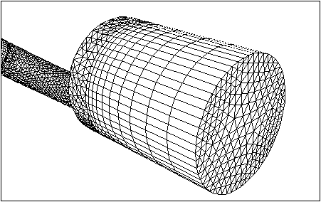
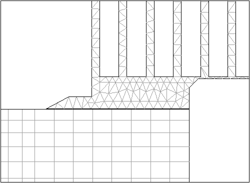
Figure 7.69: Surface Mesh shows the surface mesh for a portion of a grid containing hexahedra, pyramids, tetrahedra, and prisms that was created on a plenum feeding a valve-port cylinder.
The less complicated plenum pipe on the left of the figure is meshed using hexahedral cells.
The more complex valve port (valve not visible because it is inside the surrounding pipe) is meshed using tetrahedra.
Pyramids are used as a transition between the hexahedral grid for the plenum and the tetrahedral grid for the valve port. This transition occurs where the triangular and quadrilateral faces meet in the middle of the figure.
Additionally, the quadrilateral faces produced by extending triangular faces in the cylinder (that is, the quadrilateral sides of the resulting prism wedges) can be seen in the far right of the figure.
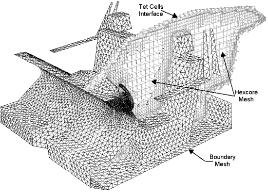
The hexcore mesh features a tetrahedral/hybrid mesh adjacent to walls and a Cartesian mesh in the core flow region. Figure 7.70: Hexcore Mesh shows the typical hexcore mesh. The hexcore meshing scheme creates a mesh consisting of two regions:
An inner region composed of regular Cartesian cells.
An outer region consisting of tetrahedral elements.
Wedge elements are created only when boundary layers are attached on faces pre-meshed with triangular elements. It combines the automation and geometric flexibility of tetrahedral/hybrid meshes with greatly reduced cell counts in many applications. The hexcore mesh is most beneficial in geometries with large open spaces, as in automotive, aerospace, and HVAC applications. Refer to Generating the Hexcore Mesh for details.
CutCell meshing is a general-purpose hex-dominant meshing technique that can be used instead of tetrahedral or hexcore meshing, without requiring a very high-quality surface mesh as a starting point. This method uses a direct surface and volume approach without the need of cleanup or decomposition, thereby reducing the turnaround time required for meshing. A key feature is the large fraction of hex cells in the mesh.
Refer to Generating the CutCell Mesh for details.
The Rapid Octree mesher enables a fast hexahedral mesh generation with two choices of boundary treatment methods to resolve the geometry. The two boundary treatment methods are:
boundary projection to create a single prismatic layer on the surface with optional local refinements
Cartesian snapping of the closest node onto the boundary for constant-size surface mesh generation
The generated mesh topology is very similar to the hexcore mesh generation and provides a mixed hexahedral and (for transitional cells) polyhedral cell description. The method used for the evaluation of cell quality is changed to ortho skew by default at the end of the meshing process (for details about quality, see Quality Measure). Since the mesh generation is designed to scale on clusters that include thousands of cores, it is very well suited for the generation of meshes with a very high cell count for scale-resolving simulations (for example, automotive external flows), as well as for any application where geometric defeaturing can be accepted to gain robustness and speed.
As the meshes are close to being uniform in the streamwise, spanwise, and wall normal directions, they are most suitable for Wall-Function LES (WFLES). A minimum mesh resolution for boundary layers would be 5x5x5 cells per boundary layer volume.
Refer to Generating Rapid Octree Meshes for details.
Additional meshing tasks that can be handled are:
If you have a complete volume mesh and want to extend some portion of the domain (for example, increase the length of an inlet pipe), you can grow one or more layers of prisms from the current external (quadrilateral or triangular) boundary.
Figure 7.73: Extending an Existing Tetrahedral Mesh Using Prisms shows a region of prisms (wedges) extended from the triangular face zone that bounds a tetrahedral region.
Unless there is a reason to use hexahedral cells in the quad regions, it is preferable to convert a mixed tri/quad boundary mesh to an all-tri boundary mesh and then create a tetrahedral mesh for a 3D boundary mesh consisting of only triangular faces.
Use the Triangulate Zones dialog box or the command
/boundary/remesh/triangulateto convert quad face zones to tri face zones.You can then use the Boundary Improve dialog box to improve the skewness of the triangular boundary zone created.
You may choose to use a non-conformal interface to define the computational domain. This type of interface enables you to relax the requirement for point-to-point matching at the interface between the meshes, as illustrated in Figure 7.74: Example of a Non-Conformal Interface.
This feature of relaxing the requirement for point-to-point matching at the interface between the meshes is particularly useful in parametric studies where you want to change an isolated region of the domain without changing the entire mesh. The procedure is as follows:
Read the meshes in meshing mode in Fluent. These meshes need not share nodes, edges, faces, or cells.
Create the volume mesh using an appropriate meshing strategy. You can also create domains for each independent mesh region and mesh the individual domains separately.
Separate the region of non-conformal interface into new face zones. Use > to change the face zone type of the two surfaces that will be treated as non-conformal to interface.
Transfer the mesh to solution mode in Fluent and create the non-conformal interface using the Mesh Interfaces dialog box. Refer to Mesh Interfaces Dialog Box for details.
To add nodes to the mesh without specifying the faces, you can create a boundary zone in the boundary mesh (in the program that created it) just for this purpose, then you can introduce the nodes associated with these faces.
This feature is useful for clustering nodes (and therefore cells) in a controlled manner. Figure 7.75: Mesh Generated Using Isolated Nodes to Concentrate Cells shows a mesh that was generated using this method to cluster the nodes behind the wedge. A mesh that was generated for the same geometry without clustering is shown in Figure 7.76: Mesh Generated Without Using Isolated Nodes. You can follow either of the two procedures to insert isolated nodes into a mesh:
Delete the face zone before meshing.
Introduce the nodes using face zones after meshing.
Deleting the Face Zone Before Meshing
This procedure is as follows:
Delete the face zone, but leave the associated nodes. Disable Delete Nodes in the Manage Face Zones dialog box to retain these nodes.
Note: By default, the unused nodes are deleted when the faces of the zone are deleted.
Disable Delete Unused Nodes in the Tet dialog box and generate the volume mesh.
Note: By default, unused nodes will be deleted during the automatic meshing.
The nodes will be introduced when you initialize the mesh. When you use this procedure, all nodes must be inserted into the mesh or the initialization will fail.
Warning: Do not place isolated nodes too close to the boundary or to other nodes.
Introducing the Nodes Using Face Zones After Meshing
This procedure is as follows:
Create a subdomain that does not include the face zones used to control the mesh density.
Create the volume mesh using the subdomain.
Activate the global domain.
Introduce the additional nodes using the text command:
/mesh/modify/mesh-nodes-on-zone.Important: The
/mesh/modify/mesh-nodes-on-zonecommand will delete the faces associated with the face zone.
The Auto Mesh dialog box enables you to automatically create the volume mesh using the different mesh elements available. This dialog box can used for generating the volume mesh based on face zones or based on a mesh object and relevant material points. For more detail about object-based mesh generation, refer to Objects.
The generic procedure for using the Auto Mesh dialog box for creating the volume mesh is as follows:
Determine the meshing approach (face zone based or object based) and the mesh elements required for the particular case.
Open the Auto Mesh dialog box using the > menu item or from the context-sensitive menu available by right-clicking on any Mesh Object, or its Cell Zones or Volumetric Regions branch in the Outline View.
Select the appropriate option in the Object drop-down list in the Auto Identify Volume group box.
For the face zone based meshing approach, ensure that none is selected in the Object drop-down list.
Note: While performing face zone-based (non-object based) volume meshing, any zones overlapping the domain need to be resolved first.
For the object based meshing approach, select the appropriate mesh object in the Object drop-down list. Enable/disable Keep Solid Cell Zones and Keep Dead Cell Zones as required.
Tip: If you open the Auto Mesh dialog box from the context-sensitive menu in the Model tree, the Mesh Object is automatically selected.
Select the appropriate option in the Grow Prisms drop-down list in the Boundary Layer Mesh group box.
Retain the default selection of none if you do not need to grow prism layers for the current meshing approach.
Select scoped if you want to specify object-specific prism parameters. Click to open the Scoped Prisms dialog box and define the prism parameters and scope. Refer to Prism Meshing Options for Scoped Prisms for details.
Select zone-specific if you want to specify zone-specific prism parameters. Click to open the Prisms dialog box and specify the zone-specific prism parameters. Refer to Procedure for Creating Zone-based Prisms for details.
Note: Growing prisms on periodic boundaries is not supported.
Select the appropriate quad-tet transition elements from the Quad Tet Transition list. Click to open the Pyramids dialog box or the Non Conformals dialog box (depending on the selection) and specify the appropriate parameters. Refer to Creating Pyramids and Creating a Non-Conformal Interface for details.
Select the appropriate option from the Volume Fill list. Click Set... to open the Tet, Hexcore, Poly, or Poly-Hexcore dialog box (depending on the selection) and specify the appropriate parameters. Refer to Initializing the Tetrahedral Mesh, Refining the Tetrahedral Mesh, Controlling Hexcore Parameters, Steps for Creating the Polyhedral Mesh, and Generating Poly-Hexcore Meshes for details.
Note: The No Fill option is not available for object based volume meshing.
Specify the appropriate Volume Fill Options.
For the Tet or Poly methods, set the following:
Select the appropriate option for Cell Sizing.
Size Field specifies that the cell size is determined based on the current size-field.
Geometric specifies that the cell size in the interior of the domain is obtained by a geometric growth from the closest boundary according to the growth rate specified.
Set the Growth Rate required.
Specify the Max Cell Length. Click to compute the maximum cell size based on the mesh object.
For the Hexcore method, set the following:
Select the appropriate option for Type.
Retain the default selection of Octree or select the Cartesian type.
Set the number of Buffer Layers and Peel Layers.
Specify the Max Cell Length for the Cartesian approach. Click to compute the maximum cell size based on the mesh object.
Specify the Min Cell Length for the Octree approach.
For the Poly-Hexcore method, set the following:
Specify the number of Buffer Layers and Peel Layers.
Specify the Min Cell Length for the poly-hexcore approach.
The hybrid poly-hexcore volume meshing method is a combination of the existing poly and the octree hexcore meshing algorithms, and is available for serial processing only, with object based workflows when the Grow Prisms option is set to none or scoped.
While similar to the Octree mesh option, the Poly-Hexcore option leverages the use of hexcore volume meshing and uses a polyhedron transitional mesh rather than a tetrahedron transitional mesh.
Note that you can control the sizing (maximum cell length and/or growth rate) for specific regions using the text command:
mesh/tet/controls/set-region-based-sizing(for tet or poly) andmesh/hex/controls/set-region-based-sizing(for hexcore or poly-hexcore).
For object-based meshing, enable Merge Cell Zones within Regions to create a single cell zone within a region, or disable to keep the cell zones separate.
For zone-based meshing, enable Merge Cell Zones to create a single cell zone within a domain, or disable to keep the cell zones separate.
Note: For object-based meshing and parallel processing, after your mesh is distributed, this option is active automatically.
The Auto Partition (Parallel Meshing) option enables automatic decomposition of the mesh into suitable partitions for parallel meshing (see Auto Partitioning for more information). Disable this option if you are interested in only generating the volume mesh in serial mode.
Click Mesh to automatically create the mesh.
Alternatively, you can use the command
/mesh/auto-mesh to generate the mesh automatically. Specify a mesh
object name for object-based auto mesh; if no name is given, face zone based auto mesh is
performed. Specify the volume fill type to be used when prompted. Specify whether to merge the
cells into a single zone or keep the cell zones separate. For face zone based meshing, specify
whether to automatically identify the domain to be meshed based on the topology information.
Note: You can specify the meshing parameters for the mesh elements (prisms, pyramids or
non-conformals, tet, or hex) using either the respective dialog boxes or the associated
text commands prior to using the auto-mesh command.
creates sweep-like mesh for a body occupying a thin gap. You define boundary face zones for source and target such that the source face normal should point to the target. The source face mesh may be triangles or quads. Four other controls are then used by Fluent Meshing to grow the volume mesh from the source zone to the target zone.
To generate a Thin Volume Mesh:
Check the source boundary mesh to ensure that free nodes or faces with high skewness do not exist. See Manipulating Boundary Nodes and Determining Surface Mesh Quality for details.
Open the Thin Volume Mesh dialog box.
>
Select the Source Boundary Face Zone from the list.
Select the Target Boundary Face Zone from the list.
Specify the Gap Thickness.
If set to 0, the mesher will automatically calculate the gap thickness.
If non-zero, the Gap Thickness defines the maximum separation between source and target zones in the swept-mesh region.
Specify the Number of Divisions between source and target faces.
Specify the Growth Rate between adjacent layers.
Choose Remesh overlap zones behavior. Remesh overlap zones replaces any overlapped part of the surface mesh on the target and adjacent faces. Original meshes in these areas are replaced.
Click Create to calculate the thin solid mesh.
Click Draw to display the mesh in the graphics window of the user interface.
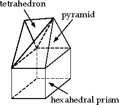
A pyramid has a quadrilateral face as its base and four triangular faces extending from the sides of the quadrilateral up to a single point above the base. See Figure 7.77: Pyramid Cell—Transition from a Hexahedron to a Tetrahedron.
To generate a conformal mesh with a region of tetrahedral cells adjacent to a region of hexahedral cells, you will first create a layer of pyramids as a transition from quadrilateral faces to triangular faces. After creating a single layer of pyramids, the resulting triangular faces will be used to create tetrahedra.
To create pyramids, you need to specify the boundary from which the pyramids will be built, the method for determining the top vertex of each pyramid, and the pyramid height.
The procedure for creating a layer of pyramids from a quadrilateral boundary zone is as follows:
Check the aspect ratio limits of the boundary face zones on which you need to build pyramids.
>
The use of a high-aspect-ratio quadrilateral for the base of a pyramid produces skewed triangular faces that can cause problems during the tetrahedral mesh generation. If the maximum quadrilateral face aspect ratio is much greater than 10, you will need to regenerate them.
If the faces were created in a different preprocessor, return to that application and try to reduce the aspect ratio of the faces in question.
If the faces were created during the building of prism layers, rebuild the prisms using a more gradual growth rate.
Select the appropriate quadrilateral boundary zones in the Boundary Zones selection list in the Pyramids dialog box.
>
Click Draw to view the selected zones.
If the quadrilateral zone you require does not appear in the list, use the
/boundary/reset-element-typetext command to update the type of the zone. It is possible that the quadrilateral zone may not be recognized the due to changes made to the boundary mesh.For example, if you separate a mixed (tri and quad) face zone into a tri face zone and a quad face zone, each of these will be identified as a mixed zone. You need to reset the element type for the quad zone for it to be recognized and included in the Boundary Zones selection list.
Select the appropriate method for determining the pyramid vertex location in the Options list. The skewness method is selected by default, and is appropriate for most cases.
Specify the height of the pyramids by setting the Offset Scaling value.
Click . The new pyramid cell zone and the new face zones created will be reported in the console. You can then use the Display Grid dialog box to view these new zones.
>
Change the boundary type of the quadrilateral base zone to the appropriate type (if necessary).
>
Note: Because you built cells next to the quadrilateral base zone, its original boundary type may no longer be correct.
Important: The pyramids should be automatically created on the appropriate side of the specified boundary zones. If the pyramids are on the wrong side, do the following:
Delete the newly created zones related to the pyramids.
Reverse the normal direction on the quadrilateral boundary where the pyramids are being built (using the Flip Normals option in the Manage Face Zones dialog box).
Recreate the pyramids.
When pyramids are generated, at least two new zones are created: a cell zone containing the pyramid cells and a face zone containing the triangular faces of the pyramids.
The following zones will be created during pyramid generation:
The cell zone containing the pyramids (
pyramid-cells-n).The face zone containing the triangular faces of the pyramid cells (
base-zone-pyramid-cap-n).For example, if the pyramids were built from the quadrilateral face zone wall-4, they will be placed in a new zone called wall-4-pyramid-cap-9 (where the
9is the zone number assigned).The face zones containing the pyramid sides that use existing faces from the original boundary mesh (
base-zone-pyramid-side:n), where,nis the zone number assigned.For example, if triangular boundary faces from the zone wall-3 are used, they will be placed in a new zone called wall-3-pyramid-side-6 (where the
6is the zone number assigned).
Important: If you include the pyramid-side boundary
zones when defining the domain in which you are going to generate
a tetrahedral mesh, the tetrahedral meshing will fail.
Most problems associated with creating pyramid layers manifest themselves in the subsequent process of generating the tetrahedral mesh.
Rapid Changes in Volume
Rapid changes in the sizes of cells have a negative influence on the convergence and accuracy of the numerical solution. The pyramid layer creation can produce rapid variations in cell volume in the following situations:
If the quadrilateral surface mesh has faces with rapid changes in size.
If there is great disparity between the sizes of the quadrilateral faces and the neighboring triangular faces used in the pyramid creation.
You can avoid the rapid variation in volume by creating quadrilateral and neighboring triangular grids with smooth variations in face size.
Intersecting Faces
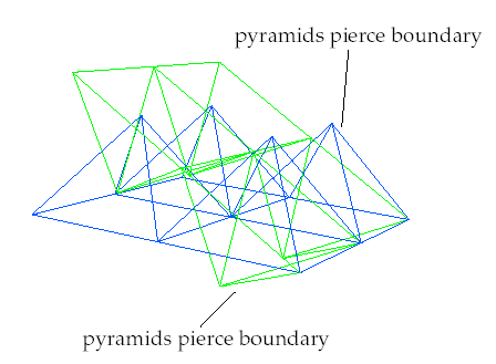
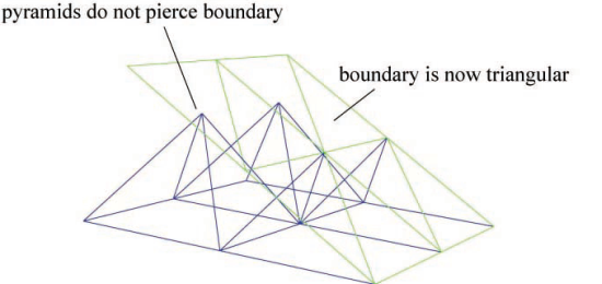
If the quadrilateral surface used to create pyramids has highly concave corners, the resulting pyramids may pierce each other and/or neighboring boundary faces:
In such cases, you can either increase the resolution to prevent
the intersections or alter the meshing strategy. An alternative is
to separate the quadrilaterals in the concave corner into another
zone (using techniques described in Separating Boundary Zones or Modifying the Boundary Mesh), create triangular faces from the quadrilateral faces using the /boundary/remesh/triangulate text command, and then
create pyramids.
The skewness-based pyramid creation will use the existing triangular faces and avoid the intersection problem (see Figure 7.79: Fixed Intersecting Pyramid Cells Using Triangular Faces).
High Aspect Ratio
Creating pyramids on quadrilateral faces with very high aspect ratios results in highly skewed triangular faces. Subsequent attempts to create a tetrahedral mesh from these elements will produce a poor-quality mesh.
Irrespective of the method used to generate the quadrilaterals, modify the meshing strategy to reduce the aspect ratio using an external grid generation package or the prism layer capability.
For meshes containing both hexahedral and tetrahedral elements, you can generate a non-conformal interface to avoid creating intermediate pyramids as transition elements between the quadrilateral and triangular surfaces. You can also choose to create a non-conformal interface when growing prisms from a boundary on a surface mesh, to avoid quad faces in the domain to be meshed. The surfaces containing quad elements will be copied and then triangulated while keeping the original surfaces intact. The free nodes of the triangulated surface will then be merged with the nodes on the original surface mesh. Both surfaces will then be converted to interface type.
The options in the Non Conformals dialog box enable you to create a non-conformal interface.
The command /mesh/non-conformals/separate enables you to separate the face zones at the non-conformal
interface between the cell zones specified. Specify the cell zones
where the interface is not conformal, an appropriate gap distance
(absolute or relative), and the critical angle to be used for separating
the face zones. The gap distance used for the separation is the larger
value of the absolute gap distance specified and the relative gap
distance times the average local edge length. You can also choose
to orient the boundary face zones after separation and additionally
write a journal file during the separation operation. This journal
file can then be read in solution mode to create the mesh interfaces
automatically.
The separated face zones will be named as follows: cell zone 1:cell zone 2-orig face zone 1 for face zone 1 attached to cell zone 1 and cell zone 2:cell zone 1-orig face zone 2 for face zone 2 attached to cell zone 2. If the separated interface zone has more than one face zone, the original face zone contributing a larger number of faces will be used for the name.
Invalid contact locations will be skipped during the separation operation. The location of the invalid contact will be reported in the console.
Many engineering systems, including power plants, climate control, and engine cooling systems typically contain heat exchangers. However, for most engineering problems, it is impractical to model individual fins and tubes of the heat exchanger core.
You can create a heat exchanger volume mesh using the options in the Heat Exchanger Mesh dialog box.
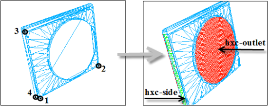
The heat exchanger mesh created contains prisms generated from a quad split surface mesh. You need to specify four points (either by selecting the locations or nodes) and the required intervals between the first selected point and the each of the remaining points to create the heat exchanger mesh. A meshed plane is created using the first three specified points and the corresponding intervals. Prisms are created on the meshed plane using the fourth point and the corresponding interval.
> >
In the Location group box, select Position or Nodes to specify the source for location coordinates.
Click or and select the four points (nodes) in the correct order.
Important: The order of selection of the points is important because the heat exchanger zone is created based on the intervals specified between the first selected point and each of the remaining points. If the points are not specified in the correct order, you will get a heat exchanger zone that is different from the required one.
In the Create By group box, select Interval or Size to setup the mesh density.
Specify the number of intervals (or mesh size) between selected points (nodes) 1–2, 1–3, and 1–4, respectively.
Enable Create Object, if you need to create a mesh object for the heat exchanger mesh zones created.
Click to preview the heat exchanger zones and modify the parameters if you are dissatisfied with the results.
Click .
Specify the prefix for the zones as required in the Object/Zone Prefix dialog box and click .
The heat exchanger zones (prefixed by hxc-) are created as shown in Figure 7.80: Creating the Heat Exchanger Mesh.
If you launched Fluent with parallel processing for meshing enabled, you will be able to distribute the mesh data across the available compute nodes, or recombine the mesh data as required. For additional information on specifying parallel processing, see Starting Ansys Fluent Using Fluent Launcher.
The following options are available for parallel meshing:
Auto partitioning enables automatic decomposition of the mesh into suitable partitions for parallel meshing. Auto partitioning is enabled using the Auto Partition (Parallel Meshing) option in the Auto Mesh dialog box. This option is available for the Poly, Poly-Hexcore, and the Octree-based Hexcore volume fill methods. When using the Tet volume fill method with zone-based or scoped prism settings, Fluent generates the prisms in parallel by default and then generates the tetrahedral mesh in serial.
Note: Auto partitioning is only available when you launch Fluent with more than one parallel processor.
Follow these steps to generate the mesh using auto-partitioning.
Prepare the surface mesh for volume meshing. Ensure that the mesh quality and connectivity are appropriate.
Enable Auto Partition (Parallel Meshing) in the Auto Mesh dialog box.
When Auto Partition (Parallel Meshing) is enabled, and after volume meshing has occurred, several elements of the graphical user interface are no longer available (Availability of Graphical User Interface Options After Parallel Meshing). Likewise, there are elements of the text user interface that are also no longer available (Availability of Text Interface Options After Parallel Meshing).
Create the volume mesh using the options in the Auto Mesh dialog box (see Using the Auto Mesh Dialog Box).
Note:Available volume meshing options include zone-specific or scoped prisms, pyramid and non-conformal quad-tet transition, and tetrahedral fill.
Improve the volume mesh using the options available, if required.
Save the mesh or case file.
After auto partitioning is enabled, and after parallel meshing has occurred, the following items in the graphical user interface are not available as noted:
| Location | Unavailable Items |
|---|---|
| Display (Ribbon) | Free Face |
| Multi Faces | |
| Patch Options (Ribbon) | Remesh |
| Separate | |
| Select File Dialog (File > Read Mesh) | Append File(s) |
| Boundary Menu | Merge Nodes |
| Intersect | |
| Create | |
| Modify Boundary Dialog (Operations) | Create |
| Merge | |
| Delete | |
| Collapse | |
| Split | |
| Swap | |
| Separate Face Zones Dialog (Options) | Prisms |
| Thin Volume Mesh | |
| Seed | |
| Mesh Menu | Prisms |
| Thin Volume Mesh | |
| Pyramids | |
| Non-Conformals | |
| Tet | |
| Hexcore | |
| CutCell | |
| Rapid Octree | |
| Create | |
| Mesh > Tools |
Tet Improve (not available for the Poly- Hexcore volume fill method, otherwise, available for the Tet volume fill method using prisms) |
| Cavity Remesh | |
| Mesh > Tools > Prism |
Improve (not available for the Poly- Hexcore volume fill method, otherwise, available for the Tet volume fill method using prisms) |
|
Split | |
|
Post Ignore | |
|
Tet Improve Cavity | |
| Modify Cells Dialog (Options) |
Split |
|
Swap | |
|
Outline View: Model context menu options |
Construction Geometry |
|
Periodicity | |
|
CAD Assemblies | |
|
Outline View: Model > Geometry Objects context menu options |
Diagnostics |
|
Convert to Mesh Object | |
|
Wrap | |
|
Remesh | |
|
Advanced | |
|
CAD Association | |
|
Outline View: Model > Mesh Objects context menu options | Diagnostics |
| Wrap | |
| Remesh Faces | |
| Join/Intersect | |
| Recover Periodic | |
| Restore Faces | |
| Advanced | |
| CAD Association | |
|
Outline View: Model > Mesh Objects > Face Zone Labels sub-level context menu options | Join/Intersect |
| Diagnostics | |
| Recover Periodic | |
|
Outline View: Model > Mesh Objects > Volumetric Regions context menu: | Compute |
| Validate | |
| Update | |
| External Baffles | |
| Setup Scoped Prisms | |
|
Outline View: Model > Mesh Objects > Volumetric Regions sub-level context menu options | Diagnostics |
| Manage | |
| Remesh Faces | |
| Scoped Prisms | |
| Tet | |
| Hexcore | |
| Auto Fill Volume | |
| CAD Association | |
|
Graphics Toolbars: Construct Geometry |
|
|
Graphics Toolbars: Loop Selection Mode |
|
|
Graphics Toolbars: Miscellaneous Portions of the Context Toolbar |
|
After auto partitioning is enabled, and after parallel meshing has occurred, the following items in the text user interface are not available as noted:
| TUI Menu | Command | Status |
objects/ | create | available |
create-and-activate-domain | not available | |
create-groups | not available | |
create-intersection-loops | not available | |
create-multiple | available | |
create-new-mesh-object/ | not available | |
check-mesh | available | |
delete | available | |
delete-all | available | |
delete-all-geom | available | |
delete-unreferenced-faces-and-edges | available | |
extract-edges | available | |
improve-feature-capture | not available | |
improve-object-quality | not available | |
join-intersect/ | not available | |
labels/ | not available | |
list | available | |
merge | not available | |
merge-edges | not available | |
merge-voids | not available | |
merge-walls | available | |
remove-gaps/ | not available | |
rename-cell-zone-boundaries-using-labels | available | |
rename-object | available | |
rename-object-zones | available | |
rotate | available | |
scale | available | |
separate-faces-by-angle | not available | |
separate-faces-by-seed | not available | |
set/ | not available | |
sew/ | not available | |
summary | available | |
translate | available | |
update | available | |
volumetric-regions/ | not available | |
wrap/ | not available | |
mesh/ | ||
auto-mesh-multiple-objects | not available | |
auto-prefix-cell-zones | not available | |
cavity/ | not available | |
create-heat-exchanger | not available | |
cutcell/ | not available | |
domains/ | available | |
laplace-smooth-nodes | not available | |
manage/active-list | available | |
manage/adjacent-face-zone | available | |
manage/auto-set-active | available | |
manage/change-prefix | available | |
manage/change-suffix | available | |
manage/copy | available | |
manage/delete | available | |
manage/get-material-point | available | |
manage/id | available | |
manage/list | available | |
manage/merge | available | |
manage/merge-dead-zones | available | |
manage/name | available | |
manage/origin | available | |
manage/revolve-face-zone | available | |
manage/rotate | available | |
manage/rotate-model | available | |
manage/scale | available | |
manage/scale-model | available | |
manage/set-active | available | |
manage/translate | available | |
manage/translate-model | available | |
manage/type | available | |
modify/extract-unused-nodes | not available | |
modify/list-skewed-cells | not available | |
modify/repair-negative-volume-cells | not available | |
non-conformals/ | not available; available when Auto Partition is disabled | |
pyramid/ | not available | |
prepare-for-solve | available | |
prism/ | available | |
prism/create | not available | |
prism/mark-ignore-faces | not available | |
prism/mark-nonmanifold-nodes | not available | |
prism/controls/ | not available | |
poly/ | not available | |
repair-face-handedness | not available | |
selective-mesh-check | not available | |
scoped-prisms/ | not available | |
tet/ | not available | |
thin-volume-mesh/ | not available | |
boundary/ | ||
auto-slit-faces | not available | |
check-boundary-mesh | not available | |
check-duplicate-geom | not available | |
clear-marked-nodes | not available | |
compute-bounding-box | not available | |
count-free-nodes | not available | |
count-marked-faces | not available | |
count-unused-bound-node | not available | |
count-unused-faces | not available | |
count-unused-nodes | not available | |
create-revolved-surface | not available | |
create-swept-surface | not available | |
delete-all-dup-faces | not available | |
delete-duplicate-faces | not available | |
delete-free-edge-faces | not available | |
delete-island-faces | not available | |
delete-unconnected-faces | not available | |
delete-unused-nodes | available | |
feature/ | not available | |
fix-mconnected-edges | not available | |
improve/ | not available | |
jiggle-boundary-nodes | not available | |
make-periodic | not available | |
mark-duplicate-nodes | not available | |
mark-face-intersection | not available | |
mark-face-proximity | not available | |
mark-faces-in-region | not available | |
manage/auto-delete-nodes? | available | |
manage/change-prefix | available | |
manage/change-suffix | available | |
manage/copy | available | |
manage/create | available | |
manage/delete | available | |
manage/flip | available | |
manage/id | available | |
manage/list | available | |
manage/merge | available | |
manage/name | available | |
manage/origin | available | |
manage/orient | available | |
manage/remove-suffix | available | |
manage/rotate | available | |
manage/rotate-model | available | |
manage/scale | available | |
manage/scale-model | available | |
manage/translate | available | |
manage/translate-model | available | |
manage/type | available | |
manage/user-defined-groups/ | available | |
mark-duplicate-nodes | not available | |
mark-face-intersection | not available | |
mark-face-proximity | not available | |
mark-faces-in-region | not available | |
merge-nodes | not available | |
merge-small-face-zones | not available | |
merge-nodes | not available | |
merge-small-face-zones | not available | |
orient-faces-by-point | not available | |
project-face-zone | not available | |
recover-periodic-surfaces | not available | |
refine/ | not available | |
remesh/ | not available | |
resolve-face-intersection | not available | |
scale-nodes | not available | |
separate/ | not available | |
set-periodicity | not available | |
slit-boundary-face | not available | |
smooth-marked-faces | not available | |
unmark-selected-faces | not available | |
wrapper/ | not available |
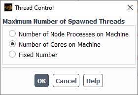
You can control the maximum number of threads on each machine by using the Thread Control dialog box (Figure 7.81: The Thread Control Dialog Box).
Parallel → Thread Control...
You have the following options when using the Thread Control dialog box:
Number of Node Processes on Machine
When this option is chosen, the maximum number of threads on each machine is equivalent to the number of Ansys Fluent node processes on each machine.
When the mesh data is distributed across multiple nodes, then each node will spawn a single node process. When the mesh data is not distributed (i.e., resides only on a single node), however, then the node will spawn to the total number of node processes. Consider using this option to potentially increase the speed of checking the mesh and its quality when the mesh is not distributed.
Number of Cores on Machine
This is the default option. When this option is chosen, the maximum number of threads on each machine is equivalent to the number of cores on the machine. Ansys Fluent obtains the number of cores from the operating system. This may be applicable when the multi-threaded part of the calculation is dominating the computation time, and you want to take full advantage of computational resources.
When the mesh data is distributed across multiple nodes, each node will spawn to the ratio of the maximum number of cores and the number of compute nodes. When the mesh data is not distributed (i.e., the mesh data resides only on a single node, e.g. node-0), then node-0 will spawn to the maximum allowed number of open multi-processing threads.
Fixed Number
When this option is chosen, you may specify the maximum number of threads that can be spawned on each machine in the number-entry box below Fixed Number. This may only be applicable when you want to have fine control of the number of threads on each machine; it is not recommended in general.
When the mesh data is distributed across multiple nodes, each node will spawn to the quotient of the Fixed Number and the number of compute nodes. When the mesh data is not distributed (i.e., resides only on a single node), however, then each node will spawn to the Fixed Number.


