


CutCell meshing is a general purpose hex-dominant meshing technique. The CutCell meshing algorithm is suitable for a large range of applications, and due to the large fraction of hex cells in the mesh, often produces better results than regular tetrahedral meshes. This method can be used instead of tetrahedral or hexcore meshing, without requiring a very high quality surface mesh as a starting point. Also, this method uses a direct surface and volume approach without the need of cleanup or decomposition, thereby reducing the turnaround time required for meshing.
The following sections are described in this chapter:
The CutCell meshing process involves the following approach:
Objects, material points (optional), and size functions are defined.
The initial size of the Cartesian grid is computed based on the minimum and maximum size set for the size functions.
A uniform Cartesian grid is created within the bounding box for the geometry.
The base size for the Cartesian grid is computed from the minimum and maximum size specified in the Size Functions dialog box as follows:
Note: You should maintain the ratio between the base size and the global minimum size such that Base Size = 2n × Min Size. This ensures that the correct minimum size is used during the CutCell meshing.
Warning: During initialization, the Cartesian grid created will contain the maximum number of Cartesian cells possible for the computed base size. If the cell count of the initial Cartesian grid exceeds the limit, use the command
/mesh/cutcell/set/max-initial-cellsto set a more appropriate number.The size function values are computed and the grid is then adaptively refined based on the local size function values.
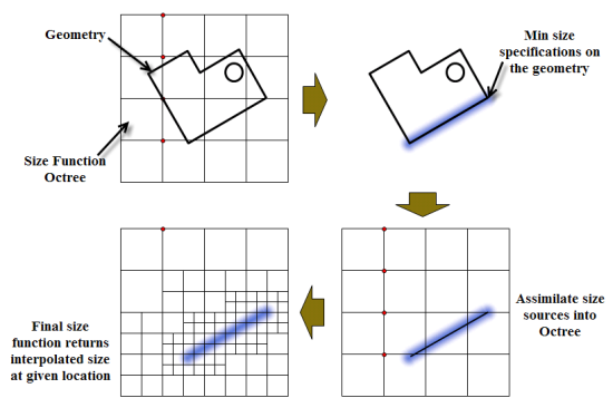
Figure 7.111: Schematic Representation of the Cartesian Grid Refinement Using Size Functions shows a schematic representation of the refinement using size functions. The size source specified via the size functions will be assimilated into the size function octree. The final mesh at respective locations will reflect an interpolated size based on the size functions.
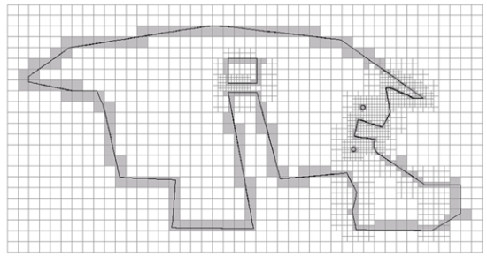
Figure 7.112: Mesh After Refinement shows the mesh after refining the initial grid based on size functions.
The cells intersected by the geometry are marked. Only nodes on marked cells are considered for projection. The nodes are projected to the geometry (corner, edge, and face in order of reducing priority).
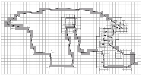
Figure 7.113: Mesh After Projection shows the mesh after node projection.
The edges intersected by the geometry are identified. Mesh edges to be preserved/recovered are determined, and are used to construct mesh faces. Once the mesh faces are identified, cells are decomposed to recover these faces. The cells are decomposed based on a number of templates.
Note: The CutCell mesher may have problems capturing features like acute internal and external face angles (for example, trailing edges of fins, wheel-ground intersections). If such features are not recovered properly, the prisms generated at such locations are most likely to have bad quality.
In such cases, you can use the
set-thin-cut-edge-zonescommand (see Resolving Thin Regions) and specify the edges where the feature capturing fails, and then regenerate the mesh.The quality of the cells thus generated is improved.
You can set the default parameters to be used for improving the CutCell mesh using the command
/mesh/cutcell/set/set-post-snap-parameters. This command sets the quality limits and other parameters relevant to the node movement and cavity remeshing that are performed to improve quality.Cells are separated into cell zones based on the respective objects and material points (if any). When a cell has a vertex that lies out of the object while the other lies within the object, the cell will be decomposed further to represent the boundary crossing the cell. A cell included in multiple objects will be included with the object having the highest priority.
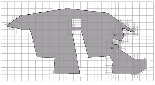
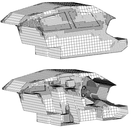
Figure 7.114: Cells Separated After Decomposition shows the cells separated into respective cell zones after decomposition.
Dead zones are generally deleted (
auto-delete-dead-zones?is enabled by default). Solid zones will be retained or deleted, depending on the setting ofauto-delete-solid-zones?(disabled by default).The boundary mesh is recovered and separated based on the underlying geometry.
Faces whose adjacent neighboring cells are in different cell zones automatically constitute the boundary mesh.
The neighboring cells of a face on an internal baffle are in the same cell zone. In such cases, faces close to and nearly parallel to the baffle surface are recovered to represent the baffle surface.
As each cell zone is a closed region, the mesh boundary is conformal.
The boundary zone types are assigned based on the underlying geometry zone type. Figure 7.115: CutCell Mesh After Boundary Recovery shows the CutCell mesh after the boundary mesh is recovered.
Note: The CutCell mesher will assign the type wall on the surface recovered over a geometry zone of the type internal (for example, baffles) and the type geometry.
The CutCell dialog box and the commands in the /mesh/cutcell menu enable you to perform various tasks related to generating the CutCell mesh.
You can use in the CutCell dialog box to generate the CutCell mesh based on the objects and material points selected.
The generic procedure for generating the CutCell mesh is as follows:
Define the objects.
Right click on Model in the Outline View and select Object Management... to open the Manage Objects dialog box. See Using the Manage Objects Dialog Box.
Make sure the objects are appropriately defined (see Object Attributes for details).
Create capping surfaces if required (see Patching Tools for details).
Important: The objects defined include the corresponding edges that are used for capturing features during the CutCell mesh generation. If you are starting from an earlier setup, you may need to add the appropriate edge zones to the object before proceeding. Several options for creating the Edge Zones are described in Extract Edge Zones.
Define the material points, if needed.
Right click on Model in the Outline View and select Material Points... to open the Material Points dialog box.
Make sure the material points are appropriately defined (see Creating Material Points for details).
Define the size functions as appropriate (see Defining Size Functions for details).
Right click on Model in the Outline View and select Functions from the Sizing context menu to open the Size Functions dialog box.
Make sure the size functions are appropriately defined.
Select the objects and material points to be used for the CutCell mesh generation in the CutCell dialog box.
From the menu, select to open the CutCell dialog box.
Select the appropriate objects in the Objects selection list.
Select the appropriate material points in the Material points selection list.
Enable Keep Solids Cell Zones in the Options group box, if required.
Click in the CutCell dialog box.
The face zones are separated by cell neighbor and normals on face zones connected to the fluid cell zones are oriented into the fluid zone. A face zone group is created for the face zones of each fluid cell zone. Additionally, the defaults for post volume mesh prism generation will be set (see Generating Prisms for the CutCell Mesh for details).
Right click on Model in the Outline View and select Prepare for Solve.
Operations such as deleting dead zones, deleting geometry objects, deleting edge zones, removing face/cell zone name prefixes and/or suffixes, deleting unused faces and nodes are performed during the cleanup operation.
Generate prism layers, if required.
Click to open the Prisms dialog box.
Examine the face zone group created for the face zones of the fluid cell zones and determine the face zones for which prism meshing parameters are to be specified.
Specify the prism meshing parameters as appropriate and click
Click in the Prisms dialog box.
Verify the quality of the CutCell mesh and perform quality improvement operations, if required.
Note: Use the > > menu item with the Write As Polyhedra option enabled to write the case file in the format that can be read in solution mode in Fluent.
Certain geometries may have components that have zero-thickness. Such configurations can be handled during the CutCell meshing process. There are two types of zero-thickness walls:
Baffles (zero-thickness walls having the same fluid/solid zone on either side)
Interior walls (zero-thickness walls having different fluid/solid zones on either side)
To allow the recovery of baffles, any such surface must be of the type internal, which will be recovered as a wall. For jump conditions, the surface must be of one of the types fan, radiator, or porous-jump, which will be recovered based on the type defined. All such surfaces should be included in the object defined. If not, the surface will not be recovered.
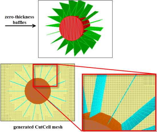
The recovered surface for the zero-thickness baffles will be prefixed by cutcell-two-sided in the generated CutCell mesh.
Figure 7.116: Mesh Generated for Geometry Having Zero-Thickness Baffles shows an example where the CutCell mesh has been generated for a stirrer geometry having zero-thickness baffles.
For interior walls, you can define two objects, each including the zones comprising the respective domains. Hence, the interior wall will appear in both objects defined, and will be recovered properly.
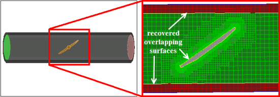
Overlapping surfaces are surfaces from independently defined objects which partially or fully overlap. To allow the recovery of overlapping surfaces as a separate surface, the overlapping walls must be included in both defined objects. The distance between such surfaces must be at least ten times smaller than the minimum size set to avoid “trapped" cell zones. The overlapping surface will be included with the recovered boundary from the object having a higher priority value.
Figure 7.117: Recovering Overlapping Surfaces shows an example where the CutCell mesh has been generated for a butterfly valve. The overlapping surfaces between the valve and flow region as well as the pipe walls and flow region are recovered.
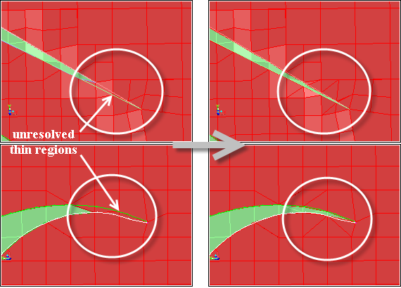
Surfaces in close proximity constitute thin regions in the mesh. Examples of thin regions include sharp corners, trailing edge configurations, and so on. Such configurations may not be recovered accurately enough by the CutCell mesher, and surface elements may span between nodes on the proximal surfaces.
You can explicitly define thin regions that need to be resolved when the CutCell mesh is generated.
The command
/mesh/cutcell/set/set-thin-cut-face-zonesenables you to specify the face zones constituting the thin regions to be recovered.The command
/mesh/cutcell/set/set-thin-cut-edge-zonesenables you to specify edge zones defining the features to be recovered in thin regions.
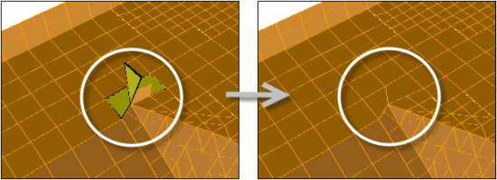
Figure 7.118: Resolving Thin Regions shows an example where the thin regions have been resolved during the CutCell meshing process.
The menu item opens the Auto Node Move dialog box, which you can use to improve the CutCell mesh quality.
The following text commands also enable you to improve the CutCell mesh:
/mesh/cutcell/modify/cavity-remeshingenables you to use the Cavity Remeshing utility to improve the CutCell mesh quality near the boundary. Specify the cell zones to be improved and the quality limit as appropriate. For details on the options available, refer to Cavity Remeshing.
Note: Face zones of type internal are recovered as type wall in the cutcell mesher. These should be reset to type internal before using the cavity remesher.
/mesh/cutcell/modify/rezone-multi-connected-facesenables you to resolve multi-connected configurations on the CutCell boundary. Specify an appropriate value for the critical count for contiguous manifold faces.
An example is shown in Figure 7.119: Rezoning Multiply Connected Faces where the multiply connected faces around the surface are removed.
After generating the CutCell mesh, you can perform cleanup operations such as deleting dead zones, deleting geometry objects, deleting edge zones, removing face/cell zone name prefixes and/or suffixes, deleting unused faces and nodes. These operations can be performed by selecting in the context menu under Model in the Outline View.
Note: It is recommended that you use the Delete option in the Manage Cell Zones dialog box
or the command /mesh/manage/delete to delete
cell zones in the CutCell mesh, instead of the option or the /mesh/clear-mesh command.
After generating the CutCell mesh, the face zones are separated by cell neighbor and normals on face zones connected to the fluid cell zones are oriented into the fluid zone. A face zone group is created for the face zones of each fluid cell zone. Additionally, the defaults for post volume mesh prism generation will be set. These include the following prism controls to reduce stair-stepping of prism layers:
Disable edge swapping.
/mesh/prism/controls/improve/edge-swap?
no
Disable face smoothing.
/mesh/prism/controls/face-smooth?
no
Set the skewness threshold for edge swapping and edge and node smoothing to
0.95./mesh/prism/controls/improve/swap-smooth-skew 0.95Ensure that shrinkage for prism layers is enabled.
/mesh/prism/controls/proximity/allow-shrinkage?
yes
Set the smoothing rate (rate at which shrinkage is propagated laterally) to
1.2./mesh/prism/controls/proximity/smoothing-rate 1.2Disable ignoring of nodes that have poor normals.
/mesh/prism/controls/normal/ignore-invalid-normals?
no
Set the cell quality criterion for smoothing and quality checking to
0.999./mesh/prism/controls/improve/max-allowable-cell-skew 0.999Enable smoothing of normals along the feature lines of the base face zones.
/mesh/prism/controls/improve/identify-feature-line?
yes
Set the maximum allowable skewness for cap faces after smoothing to
0.999./mesh/prism/controls/improve/max-allowable-cap-skew 0.999Set the quality method to Orthoskew.
/mesh/prism/quality-method orthoskewEnable the improvement of cell quality for every prism layer. This will involve smoothing of normals in the current layer and perturbation smoothing to improve cell quality in the lower layer.
/mesh/prism/controls/improve/cell-quality-improve?
yes
Enable the adjustment of prism heights at prism cap corners to improve cell quality.
/mesh/prism/controls/improve/corner-height-weight?
yes
Disable forcible smoothing of cells if cell quality remains bad after regular smoothing.
/mesh/prism/improve/smooth-brute-force?
no
You can generate prism layers on the appropriate face zones as follows:
Click in the CutCell dialog box to open the Prisms dialog box.
Examine the face zone group created for the face zones of the fluid cell zones and determine the face zones for which prism meshing parameters are to be specified.
Specify the prism meshing parameters as appropriate and click
Note: Hanging-node cells on a boundary for which prism generation has been assigned, will be triangulated before the prism generation starts.
Important: Attempting to grow thicker prism layers in areas where the aspect ratio of the base to the prism cap is very large may result in an invalid mesh. In such cases, (for example, external flow problems) it is recommended that aspect ratio based growth be used to avoid problems with invalid meshes.
Click in the Prisms dialog box.
As the volume mesh already exists, a Question dialog box will appear, asking if you want to morph the existing volume mesh. Click Yes to generate the prism layers.
Alternatively, use the command
/mesh/cutcell/create-prismto create the prism layers. Specify the cell zones into which the prism layers are to be grown. The gap factor controls the number of elements in regions of proximity.Note: If the cell aspect ratio exceeds the specified maximum aspect ratio, a message will appear during the prism meshing process, indicating that shrinkage was limited by the maximum aspect ratio specified.
You could also reduce the gap factor to avoid the cell aspect ratio exceeding the specified maximum aspect ratio. Reducing the gap factor (for example, a value of 0.5) may improve the quality, but could have a negative impact on the robustness of the morphing. A higher value (for example, 1.5) is generally more robust, but may not result in the best mesh quality.
Note: During the surface mesh morphing, only the boundaries of face threads will be treated as features.
When prism layers are grown into cell zones sharing a face, the prisms will be imprinted on the shared face.
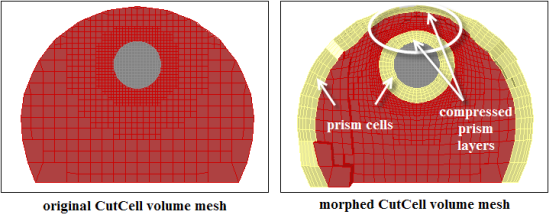
Figure 7.120: Generating Prisms for the CutCell Mesh shows the prism layers created for the CutCell mesh. The prism layers will be compressed in regions of proximity and bad normals. Note that local stair-stepping may occur in areas of poor quality.
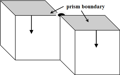
When prism layers are grown into two volumes sharing an edge, stair-stepping will occur at the common vertex between the volumes (Figure 7.121: Prism Growth Limitations—Volumes Sharing an Edge).
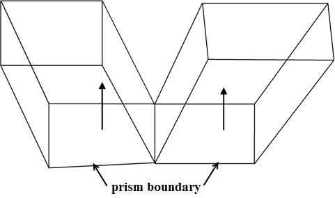
When prism layers are grown into two volumes sharing an edge, stair-stepping will occur at the nodes on the common boundary (Figure 7.122: Prism Growth Limitations—Volumes Sharing an Edge).
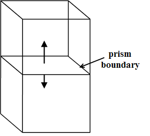
Prism layers cannot be grown on both sides of a surface shared by adjacent volumes (Figure 7.123: Prism Growth Limitations—Volumes Sharing the Prism Base).
A combination of node movement and cavity remeshing is carried out to improve the CutCell mesh quality after the prism layers have been generated. The parameters for improving the CutCell mesh quality can be specified using the command
/mesh/cutcell/set/set-post-morph-parametersprior to creating the prism layers. The quality method considered is that set by the/mesh/cutcell/set/set-cutcell-quality-methodcommand.
Ensure that the quality of the prisms created is appropriate. If the quality of the prism cells is low, you can use post-prism smoothing to improve the quality. Use the options in the Prism Improve dialog box or text commands such as
/mesh/prism/improve/smooth-improve-prism-cellsto improve the prism cell quality.To further improve the CutCell mesh using the command
/mesh/cutcell/modify/post-morph-improve, modify the relevant parameters using the command/mesh/cutcell/set/set-post-morph-parameters. The quality considered is that set by the/mesh/cutcell/set/set-cutcell-quality-methodcommand.Note: This operation uses a combination of node movement and cavity remeshing to improve the CutCell mesh quality. For details on the relevant parameters, refer to Moving Nodes and Cavity Remeshing.
Note: It is recommended that you use the
/mesh/cutcell/modify/post-morph-improvecommand for cell zones other than the prism cells.
The Cut-Tet workflow enables you to create a tetrahedral, hexcore, or prism mesh based on a triangulated and improved CutCell surface mesh. The initial requirement is the generated CutCell mesh.
The generic workflow is as follows:
Make the CutCell boundaries conformal to remove hanging-nodes.
/mesh/cutcell/modify/split-boundary cutcell-* ,The command
/mesh/cutcell/modify/split-boundarycreates a copy of the specified CutCell boundary zones and makes the boundary mesh conformal at the hanging-nodes on the copied zones. The new zones will be named based on the original zone names prefixed by split-.Clear the volume mesh.
/mesh/clear-meshTriangulate the split CutCell boundary zones.
/boundary/remesh/triangulate split-* , yesThe split CutCell boundary zones will be replaced by the corresponding triangulated boundary zones.
Improve the boundary mesh by swapping edges based on a node degree value other than 6. The node degree is defined as the number of edges connected to the node.
/boundary/improve/degree-swapUse boundary smoothing operations to further improve the boundary mesh quality (see subsequent step).
Note: Do not use the
/boundary/improve/swapoperation immediately after the/boundary/improve/degree-swapoperation, as this will restore the original degree configurations.Improve the triangulated boundary mesh further using any of the following options available:
Use wrapper smoothing operations to improve the boundary mesh quality.
Change the type of the triangulated boundary mesh to wrapper.
Use the wrapper post improve operations to improve the boundary mesh quality. Refer to Diagnostic Tools or Improving the Mesh Objectsfor detailed descriptions of the options available.
Note: Make sure the original geometry is retained when the CutCell mesh is generated, this required for reprojection when using the post improve operations.
Use operations like improving based on boundary mesh quality, smoothing, and swapping to improve the boundary mesh quality. Refer to Improving Boundary Surfaces for the detailed descriptions of the options available.
Use surface remeshing with the size functions defined for the CutCell mesh.
Extract edge zones from the triangulated boundary mesh.
This enables you to maintain the boundary node locations on the remeshed faces and facilitates the connection between the remeshed faces using simple node merge operations.
Split the edges having sizes bigger than the size function defined using the Scheme command
 (ti-refine-edge-threads-by-sf (get-edge-zones-of-filter
'split-*))
Remesh the triangulated boundary mesh using the defined size functions using the Scheme command
(ti-remesh-multiple-threads
(get-face-zones-of-filter 'split-*) #f #t "none" #t)
This enables you to remesh multiple surfaces in a single operation.
Tip: You can also add a meshed size function on the edge zones extracted from the triangulated boundary mesh to improve the quality.
Merge duplicate boundary nodes on the remeshed boundary zones.
Generate the tetrahedral/hexcore/prism mesh. Refer to Generating Tetrahedral Meshes, Generating the Hexcore Mesh, and Generating Prisms for the detailed descriptions of the meshing options available. You can also use the Auto Mesh option (see Using the Auto Mesh Dialog Box) for generating the mesh.
Note: To generate the tetrahedral mesh using the defined size functions, use
(tgsetvar! 'impose/cell-size-method 4). This will also respect the body of influence size functions defined for the CutCell meshing.You can also use additional operations during the volume meshing process, as appropriate. For example,
/mesh/manage/merge-dead-zonescan be used to merge dead zones having a cell count lower than the specified threshold value, with the adjacent cell zone.Improve the mesh quality using the various improvement options available. Refer to Improving the Mesh for detailed descriptions of the options available.