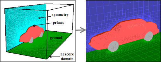
Hexcore meshing is a hybrid meshing scheme that generates axis-aligned Cartesian cells inside the core of the domain and tetrahedral cells close to the boundaries. Hanging-node (or H-) refinements on the Cartesian cells enable efficient cell size transition from boundary to interior of the domain. This results in fewer cells with full automation and can handle complex geometries, internal walls and gaps.
The hexcore meshing scheme is applicable to all volumes but is useful mainly for volumes with large internal regions and few internal boundaries such as intrusions or holes. The Hexcore submenu contains options to control the hexcore mesh generation. The starting point is a valid surface mesh.
You can control the general shape, size, and density of the
core, as well as the size of elements created at the outer boundary of the core using the
parameters in the Hexcore dialog box and the commands in the
/mesh/hexcore/ menu.
There are two approaches available for generating the hexcore mesh.
The default Cartesian type.
The Octree type which supports the size controls defined, or the computed size field. This results in faster hexcore mesh generation. However, it does not support generation of hexcore mesh up to boundaries.
When the Cartesian type is used, internally the following steps are taken to generate the hexcore mesh:
Generating initial Cartesian cells inside a bounding box (or the region specified) around the volume to be meshed.
Marking both, the Cartesian cells that intersect the boundary mesh and those cells having sizes larger than the average size of the faces they intersect.
Marking additional buffer-layer cells adjacent to the cells marked in Step 2 (if specified).
Marking additional cells to enforce one-level refinement difference between adjacent cells.
Subdividing all marked (in steps 2–4) cells and repeating steps 2–5 until the local face size criteria is met.
Deleting cells that intersect or are within some distance to the closest face on the surface mesh.
Triangulating the external surface of the hexcore by converting quads into tri interface faces. The quad faces become parents (with type
parent-face) of the interface faces.Note: Pyramids are not used for the transition from the hexcore to the tetrahedral cell regions.
Smoothing the interface faces (if interface smoothing is enabled).
Initializing and refining the tetrahedral cells between the interface faces and the boundary mesh.
Note: The maximum skewness reported at the end of the refinement process is not necessarily the final maximum skewness. Sliver cells on the interfaces can be removed at a later stage.
Removing sliver cells on the interface faces.
Merging Cartesian cells with tetrahedral (and wedge, if present) cells to form contiguous cell zones.
When the Octree type is used, internally the following steps are taken to generate the hexcore mesh.
A uniform Octree domain is initialized for the region specified by the volume to be meshed.
The octants are refined to local surface mesh sizes and to respect BOI size controls, if defined.
If the size-field exists, the Octree refinement will be driven by the size-field instead.
Peel layers are enforced. Cells that intersect the surface mesh or are within some distance to the surface mesh are deleted.
Buffer layers are enforced as applicable.
The external surface of the hexcore mesh is triangulated, the quads are converted to tri interface faces. The quad faces become parents (with type
parent-face) of the interface faces.Note: Pyramids are not used for the transition from the hexcore to the tetrahedral cell regions.
The interface faces are smoothed (if interface smoothing is enabled).
The tetrahedral cells between the interface faces and the surface mesh are generated.
The sliver cells on the interface faces are removed.
The hex cells are merged with tetrahedral cells to form contiguous cell zones.
Important: If prism parameters have been attached to boundary zones, the prism layers will first be generated. The hexcore meshing procedure will then be applied to the resulting prism caps, along with the other boundary zones that were not involved in the prism mesh generation.
To create a hexcore mesh using the Hexcore dialog box, do the following:
Read in a boundary mesh and check and improve its quality, if necessary.
(optional) Split any quad faces in the boundary mesh into triangular faces using the
/boundary/remesh/triangulatecommand.By default, quad faces are not allowed while initializing the hexcore mesh.
Alternatively, use the command
/mesh/non-conformals/controls/enable?to enable the creation of a non-conformal interface.If this option is enabled, all the surfaces having quad elements will be copied and remeshed with triangular faces. The free nodes of the triangular mesh will be merged with the original surface mesh. The method to be used for retriangulation can be specified using the command
/mesh/non-conformals/controls/retri-method.The
quad-splitmethod is the default method used for retriangulation. You can selectprism,quad-split, orremeshas appropriate.Select the appropriate option in the Type list.
Retain the default selection of Cartesian or select the Octree type.
Specify the hexcore parameters.
Some parameters (maximum cell length or minimum cell length) required during the hexcore meshing are automatically calculated. The hexcore meshing parameters can be changed using the Hexcore dialog box or using the commands in the
/mesh/hexcoretext menu.Note: Some operations, such as Hexcore only, are not available for object-based volume meshing. Similarly, options under the Zones group in the Hexcore dialog box, that require a zone-based workflow, have no effect for object-based volume meshing.
Click in the Hexcore dialog box to generate the hexcore mesh.
The parameters that control the hexcore mesh generation can be changed using the Hexcore dialog box. The following options are available:
The use of Maximum or Minimum cell length is determined by your choice of Type.
When using the Cartesian type, the Max Cell Length is used for generating the initial Cartesian cells.
An optimal maximum cell length can be automatically calculated for a particular mesh. Click the Compute button next to the Max Cell Length field to obtain the optimal maximum cell length for the mesh. Alternatively, specify the maximum cell length as required.
When using the Octree type, the Min Cell Length as set by the global minimum size for scoped sizing is used for generating the hexcore mesh.
Note: Changing the default Min Cell Length value will change the global minimum size for scoped sizing as well.
If a size-field has been computed, the minimum cell length will be the global minimum size specified for the size-field.
The Cartesian cells are marked (and subsequently subdivided) to satisfy the size requirement
on the boundary mesh. When there is large disparity in size distribution between the boundary mesh
and the initial Cartesian cells, there will be a rapid transition from fine to coarser cells. To
avoid this, additional layers of cells are marked adjacent to those marked by the size requirement
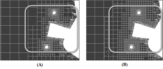
(see Figure 7.106: Hexcore Mesh Using (A) Buffer Layers = 1 (B) Buffer Layers = 2). You can control the
number of additional layers by setting the Buffer Layers in the
Hexcore dialog box. The default number of buffer layers is set to
1. Setting the number of buffer layers to zero may result in a poor quality
mesh.
Note: If the size-field has been computed and the Octree type is used to generate the mesh, the hexcore mesh size is driven by the size-field. In this case, the number of buffer layers is not required.
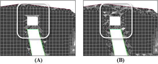
The peel layers control the gap between the hexahedra core and the geometry. After the
Cartesian cells are subdivided to meet the size requirement, the cells intersected by boundary mesh
and those within some distance to the closest face on the boundary mesh are deleted. The default
value for Peel Layers is 1, hence this distance is
assumed to be the height of an ideal tetrahedral cell on the boundary face. If Peel
Layers is set to 0, the gap size can be smaller than the ideal
height. The resulting hexcore mesh will contain the maximum number of Cartesian cells possible for
the chosen parameters.
Figure 7.107: Hexcore Mesh Using (A) Peel Layers = 0 (B) Peel Layers = 2 shows the hexcore mesh generated for different values of Peel Layers.
When using the Cartesian type, you can choose to create the hexcore mesh up to the boundary of the domain instead of creating a tetrahedral mesh at the boundary. The hexcore mesh extents can be defined by specifying a box in which the hexcore mesh is to be generated and/or a set of axis-aligned planar boundaries to which the hexahedral core is to be extended. The extents can be defined as follows:
Enable Define Hexcore Extents in the Hexcore dialog box.
Click the Specify... button to open the Outer Domain Parameters dialog box.
Enable Coordinate Extents in the Outer Domain Parameters dialog box. The minimum and maximum domain extents will be automatically updated with values slightly greater than the bounding box of the surface mesh in the domain. The coordinate extents of the hexcore outer box can also be specified as required.
Important: The hexcore mesh will extend to the defined domain extents. A warning will be displayed if the gap between the user-defined domain extents and geometric boundaries is less than 20% of size of the bounding box which contains the given geometry.
Enable Draw Outer Box and click Draw to verify that the domain extents are correctly defined.
Click Apply in the Outer Domain Parameters dialog box.
Create the hexcore mesh.
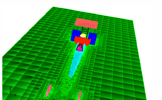
This feature is useful for the hexcore mesh generation for external flow domains (for example, external aerodynamics cases where the boundary conformity is not needed for far-field boundaries). This also helps increase the count of hexahedral cells in the mesh.
In Figure 7.108: Hexcore to the Far-Field Boundary, the hexcore mesh has been extended until the domain boundary and does not have a tetrahedral mesh at the far-field boundary.
You can use the Boundary Extents option in the Outer Domain Parameters dialog box to imprint quad faces on selected axis-aligned planar boundaries. The selected boundary will be replaced with a mix of quad- and tri-face zones. You can generate the hexcore mesh to selected boundaries as follows:
Enable Define Hexcore Extents in the Hexcore dialog box.
Click the Specify... button to open the Outer Domain Parameters dialog box.
Enable Boundary Extents in the Outer Domain Parameters dialog box and select the appropriate planar, axis-aligned boundaries to which the hexcore mesh is required.
Note: The planar boundaries must be split into separated boundary zones.
Click Apply in the Outer Domain Parameters dialog box.
The hexcore box coordinates will automatically snap to the selected boundaries.
Enable Draw Outer Box. Draw the outer box along with the selected boundaries to verify that the box snaps to the selected boundaries.
If the box does not snap to a selected boundary, it indicates that the hexcore mesh cannot be grown to the boundary. If the selected boundary zone is a plane which is misaligned with the axis, you can align it using the Auto Align option as follows:
Select the zones to be aligned in the Boundary Zones selection list.
The Auto Align group box will now be activated.
Enable Auto Align.
The recommended auto align tolerance value can be computed for the selected set of boundary zones. Click Compute to determine the recommended tolerance or enter an appropriate tolerance value.
Click Apply in the Auto Align group box to align the selected zones which are within the tolerance specified.
Warning: The Auto Align option may deform the geometry permanently. Take care while selecting the boundary zones.
Draw the outer box along with the selected boundaries to verify that the box has snapped to the selected boundaries.
Enable Delete Old Face Zones, if required and click in the Outer Domain Extents dialog box.
Create the hexcore mesh.
The newly created quad face zones will be named with the original zone names.
The hexcore mesh will extend to the selected boundaries, aligned with the X, Y, and Z axes. An example is shown in Figure 7.109: Hexcore to Boundaries.
Warning: If you attempt to use this option when the geometry is completely within the domain, an error will be reported.
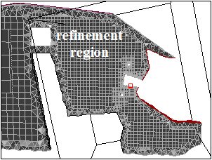
When using the Cartesian type, you can use local refinement regions to refine specific cells within the domain. During the hexcore meshing procedure, the cells within the activated local refinement regions will be refined. Currently, the only possible region shape is a box, either aligned with the coordinate axes, or oriented as required.
The region extents are defined by the center and the length of the region. The cell size within the region can be manipulated by setting the level of refinement relative to the maximum cell length in the hexcore domain. You can also orient the region as required. You can create multiple regions that overlap each other and the geometry. To create additional regions, you can copy an existing region and then modify the parameters as required. The default region includes the entire geometry.
You can use the Draw button in the Hexcore Refinement Region dialog box to display the defined region. Figure 7.110: Local Refinement Region for the Hexcore Mesh shows a refinement region defined. A sample Cartesian cell with the specified Max Length is also displayed at the center of the refinement box.