


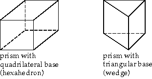
You can create prism cells starting from either quadrilateral or triangular boundary faces, or both. Prisms can be used to resolve a boundary layer region of a tetrahedral mesh. They can be used to extend some portion of a domain for which the volume mesh already exists (for example, increase the length of an inlet pipe), or to create a volume mesh by extrusion.
Figure 7.82: Prism Shapes shows the types of prisms that can be generated.
To create prisms, you need to specify the surfaces from which the prisms will be built and the parameters that control the prism growth. Details about how the parameters are used to generate the prisms are provided in The Prism Generation Process.
For zone-based prism growth, the prisms are grown from selected boundary zones. Growth parameters such as offset and growth methods, prism height, the number of layers, and the direction may be applied only to specific zones. Additional growth options including options for prism proximity detection and splitting can also be specified. Instructions for building zone-based prisms are provided in Procedure for Creating Zone-based Prisms. The additional options are described in Prism Meshing Options for Zone-Specific Prisms.
For object-based meshing, use the scoped prism process to select regions for prism creation and set up controls for the prism generation. Each control specifies the offset method, prism height, number of layers and growth rate (scoped prism uses the geometric growth method). The scope for prism creation can be set to fluid-regions, solid-regions, or specifically named-regions. Within the selected regions, you can grow prism layers on only-walls (default), all-zones, or the solid-fluid-interface. Alternatively, you can grow prism layers on selected zones (selected-face-zones) or face zone labels (selected-labels). The scoped prism controls can be read from a previously saved file or can be written to a file for further use. These options are described in Prism Meshing Options for Scoped Prisms.
Problems related to prism generation are discussed in Prism Meshing Problems.
Note: Generating prisms on periodic boundaries is not supported.
The following process is used by the mesher to build the prisms and to create a high-quality mesh.
Boundary mesh analysis:
The initial surface mesh is analyzed to determine if any adjacent zones should be projected to adjacent zones and retriangulated (if triangular), or if their faces should be used as the sides of new prism cells (if quadrilateral).
For details on determining whether to use existing boundary zones or not, see Using Adjacent Zones as the Sides of Prisms.
Prism layer growth.
Prism layers are grown one by one, based on the layer height specification. This is a multistep procedure, and hence some of the steps may be modified or skipped:
Determine the initial direction vectors so that the direction in which to build the prisms is determined. The direction methods available are discussed in Direction Vectors.
Check for proximity and determine shrinkage of prism layers based on the proximity options specified.
Determine the initial offset distances so that the mesher will know how far from the corresponding nodes on the previous layer to place the new nodes that define the prisms. See Offset Distances for details.
Smooth the initial direction vectors. See Normal Smoothing for details.
Adjust and smooth the offset distances to eliminate spikes and dips in the new prism layer. See Offset Smoothing for details
Project new nodes along the outer edges of the prism layer to adjacent zones, based on the analysis in step 1.
Create prism faces and cells using the new nodes. The new faces at the top of the prism layer are referred to as cap faces.
The new cap faces of skewness value greater than the specified threshold are improved by edge swapping or edge node smoothing.
Apply global smoothing across the new surface. This is also skewness-driven, but is based on the nodes not the faces. See for details.
Check the quality of all new cells and faces.
If quality problems are detected, prism layer creation is stopped. If more layers are to be grown, the process is repeated starting from substep (a).
Zone clean up: After all the prism layers have been grown, the new faces along the outer sides of the layers are moved to zones of the same types as the zones to which their nodes are projected. Unprojected faces are collected in a single
prism-sidezone.Retriangulation: Adjacent triangular zones that have been projected to adjacent zones are automatically retriangulated. Triangles that are overlapped by new quadrilateral faces from the prism layers are removed. Most of the original nodes are used in the new triangulation. The result is a conformal interface between the sides of the prism layers and the adjacent triangular zones.
When prisms are generated, several new cell and face zones are created. You can identify the new zones by their default names.
The cell zone containing the prisms will be named
prism-cells-#.The face zone created at the end of the last prism layer will be named
prism-cap-#.If the prism layers are bounded by one or more existing triangular face zones, each of these will be retriangulated so that the faces of the zone that are adjacent to the prisms will become quadrilateral faces, while the rest of the faces in the zone remain triangles.
If an original triangular face zone is called
symmetry, the portion of it that still contains triangles will be retained assymmetry, while the portion containing quadrilateral faces will be namedsymmetry-quad:#.Any faces that were not projected to adjacent zones (see Using Adjacent Zones as the Sides of Prisms) are collected into a zone named
prism-side-n.For a zone
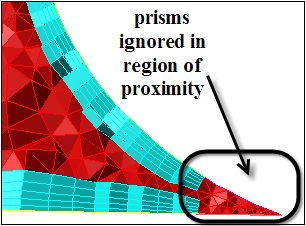
wall-#, the zone created by ignoring prism growth in the region of proximity will be named aswall-#:ignore, where,#is the zone number assigned.Important: All the ignored threads related to a base thread will be merged into a single thread by default. You can however change this using the command
/mesh/prism/controls/merge-ignored-threads?which will generate more than one thread per base thread.
To merge one or more prism cell zones with other cell zones (and merge the corresponding face zones), use the Merge option in the Manage Cell Zones dialog box.
By default, the prism-cap-# zones will be wall zones. If you do not want to include these walls in the model, change them to interior zones (or any other type) using the Manage Face Zones dialog box.
Note: If the prism mesh is generated using the Auto Mesh tool and Merge Cell Zones is enabled, the new face zones will be merged with the original boundary zones and a single cell zone will be created.
The procedure for creating prisms by setting up zone-specific parameters is as follows:
Check the boundary mesh to ensure that free nodes or faces with high skewness do not exist. See Manipulating Boundary Nodes and Determining Surface Mesh Quality for details.
Select the boundary zones from which you want to grow prisms in the Boundary Zones selection list in the Prisms dialog box.
>
Alternatively, when using Auto Mesh, select zone-specific in the Grow Prisms drop-down list and click to open the Prisms dialog box.
Important: If you read in a mesh file created in a previous version, it is recommended that you reset all the prism parameters using the command
/mesh/prism/reset-parametersbefore proceeding with setting the prism parameters.Specify prism growth parameters in the Growth tab.
Select the appropriate Offset Method and Growth Method for growing prisms.
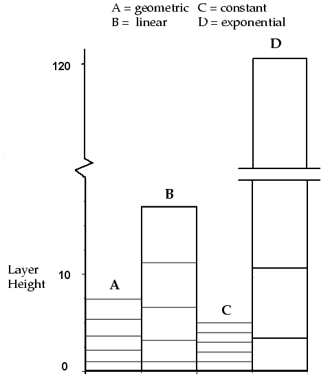
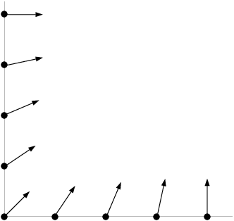
Figure 7.83: Layer Heights Computed Using the Four Growth Methods shows layer heights for all four methods, using a first height of 1 and a slope/rate/exponent of 1.2.
See Offset Distances for details.
Define the height of the first prism layer (First Height/First Aspect Ratio).
Set the growth method related parameter (Slope, Rate, or Exponent, as applicable) and the Number of Layers.
Specify options for prism growth, proximity detection, and splitting of prism layers (if needed) in the Prisms Growth Options dialog box (opened using the Growth Options... button), if required. Refer to Prism Meshing Options for Zone-Specific Prisms for details.
Click the Plot button to preview the height distribution.
For information on setting different growth parameters for different zones, see Growing Prisms Simultaneously from Multiple Zones.
Specify the direction for prism growth (see Direction Vectors).
Click the Direction tab in the Prisms dialog box to view the direction parameters.
Verify the orientation of the normals for the zones on which you want to grow prism layers. Ensure that the normals are pointing in the direction that you want to build the prisms.
You can use the Color by Normal option, accessible using the hotkey Ctrl+Shift+C then Ctrl+N to verify the normal direction.
If the boundary zone normals are incorrectly oriented, click the Orient Normals... button to open the Orient Normals dialog box. Specify the material point based on which the normals are to be oriented and click Apply.
For mesh objects, use the options in the Orient Mesh Object Face Normals group box to orient the normals.
Select the mesh object in the Object Name drop-down list.
Select Region or Material Point as appropriate, and then select the region or material point in the drop-down list.
Ensure that Select is enabled, and enable Select Walls and/or Select Baffles as needed.
Click .
Face boundary zone groups comprising the prism base zones will be created (prefixed by _prisms).
Specify the method for determining the direction of the prisms:
Select Normal in the Method list to compute normal direction vectors. This method takes into account the change in direction required for a curved region. Specify the values for the maximum angle change.
Select Uniform in the Method list to use a constant, uniform direction for flat prism regions. Specify the appropriate direction vector.
Set the parameters for prism improvement and prism projection available in the Improve and Project tabs, respectively, as required. See Using Adjacent Zones as the Sides of Prisms for more information.
Click to save your settings.
After applying your prism settings you can use the Diagnostics Tools dialog box to identify exposed quadrilateral faces (Exposed Quads) prior to generating prisms. as outlined in Using the Diagnostics Tools Dialog Box.
Save the mesh:
> >
Important: It is a good practice to save the mesh at this point. If you are dissatisfied with the prisms generated, you can read in this mesh and modify the prism parameters to regenerate the prisms.
Click to generate only the prism cell zone.
Refer to Prism Meshing Problems for suggestions on solving problems occurring during prism generation.
Alternatively, when using Auto Mesh, click and close the Prisms dialog box. The prism cells will be created first, and then the mesher will proceed to generating the tet/hexcore mesh. Refer to Using the Auto Mesh Dialog Box for details.
Check the maximum face skewness value reported in the console when the final prism layer is created, to ensure that the value is acceptable.
This is especially important if you are going to generate tetrahedral or pyramidal cells using this new boundary zone.
The new zone should not have highly skewed triangles or quadrilaterals. For more information about the quality of quadrilateral faces used for creating pyramids, refer to Creating Pyramids.
If the reported maximum skewness is too high, read the mesh file you saved after setting the prism parameters and try again with different parameters. Refer to Prism Meshing Problems for details.
A number of new zones are created when the prism generation is complete (see Zones Created During Prism Generation). If the prism-cap or prism-side face zones are not supposed to be walls (for example, if they are supposed to be simple interior zones), change them to the appropriate boundary type.
>
For most cases, performing these steps will result in an acceptable mesh of prismatic cells, but for some complex geometries, you may have to modify the procedure. If you are not satisfied with the prisms generated, you can read in the mesh you saved before generating prisms and modify the prism parameters. Refer to subsequent sections for details on modifying the prism generation parameters to create a better mesh.
The procedure for using zone-specific prism controls for creating prisms during volume meshing using Auto Mesh is described in Using the Auto Mesh Dialog Box.
This section describes the prism meshing options available for creating a prism mesh based on zone-specific settings.
This section describes the additional growth options available for creating a prism mesh based on zone-specific settings.
You can select multiple face zones for simultaneously growing prism layers. If the face zones are connected, the prisms grown will also be connected. A single zone of prism cells and a single zone of cap faces will be created for each set of simultaneously grown layers.
You can grow prisms from multiple zones with the same or different growth parameters.
To use the same growth parameters for all zones, follow the steps in Procedure for Creating Zone-based Prisms. In this case, the same number of layers are grown from all zones, and all other parameters (growth method, offset method, direction method, and so on) also remain the same.
To use different growth parameters for different zones, you can apply different growth methods, offset methods, first height, and other growth parameters (as required for the growth method selected) individually for each zone and click the Apply button in the Zone Specific Growth group box in the Prisms dialog box.
If you specify different growth parameters for different zones, all other parameters (direction method, offset method, and so on) can be set separately for each zone. In this case, the offset height of each node that is shared by multiple zones will be the average of the heights applied on the separate zones.
This produces a continuous transition between the zones (Figure 7.84: Different Growth Parameters on Adjacent Zones). Offset smoothing (see Offset Smoothing) is recommended in these cases to avoid sharp height changes at such edges.
To assign different growth controls and different offset types to different face zones, replace steps 2 and 3 in Procedure for Creating Zone-based Prisms with the following steps:
Select the zones for which you want to specify a set of growth parameters in the Boundary Zones list in the Prisms dialog box.
Set the appropriate Offset Method, Growth Method, First Height, and the related growth parameters (as required) in the Growth tab.
Specify parameters for proximity/collision detection in the Prisms Growth Options dialog box (see Detecting Proximity and Collision for details).
Important: By default, a single zone of prism cells and cap faces is generated for the simultaneously grown prism layers.
Click in the Prisms dialog box.
Repeat this procedure for other zones for which you want to apply different growth controls.
Click .
Warning: Before you click the button, ensure that all the zones for which you want to grow prisms are selected in the Boundary Zones list.
Note: When the Prisms dialog box is used to generate prism layers on multiple zones (adjacent or nonadjacent), the number of layers is determined by the chronologically last selected zone in the Boundary Zones selection list.
Important:If you specify different number of layers to be grown on adjacent zones, the same number of layers (generally the smaller number of layers) will be grown on both the zones (see Figure 7.84: Different Growth Parameters on Adjacent Zones).
If you specify different number of layers on multiple (nonadjacent) zones and use the Prisms dialog box to generate the prism layers, the same number of layers will be grown on the respective zones. The number of layers is determined by the chronologically last selected zone in the Boundary Zones selection list.
If you specify different number of layers on multiple (nonadjacent) zones and use the Auto Mesh dialog box to generate the prism layers, the prism layers will be grown separately from each zone:
Two-sided walls may be present in some models. To grow prisms on both sides of a two-sided wall (for example, growing prisms on dangling walls), do the following:
Select the two-sided wall on which you want to grow prisms from the Boundary Zones selection list.
Specify the prism growth parameters as required.
Enable Grow on Two Sided Wall in the Growth tab of the Prisms dialog box.
Click . Figure 7.86: Prism Growth on a Dangling Wall shows an example of prisms grown on a dangling wall.
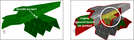
Some models may contain regions where the normals considered while growing prisms may be invalid. The normal at a particular node may be nearly tangential to the surrounding faces in the model and as a result, the prism generation may fail. For such cases, you can choose to ignore regions of the model where invalid normals exist, during prism generation. Prism layers will be grown from the remaining regions according to the specified parameters.
Figure 7.87: Ignoring Invalid Normals shows a portion of the model where the normal at the highlighted node will be nearly tangential to some of the surrounding faces. You can see that the region around this node has been ignored while creating prisms.
You can ignore regions based on normals while creating prisms as follows:
Specify the prism growth parameters.
Select the Boundary Zone containing the invalid normal and click the Growth Options... button to open the Prisms Growth Options dialog box.
Enable Ignore Invalid Normals in the General Options group box.
Click and close the Prism Growth Options dialog box.
Grow prisms as required.
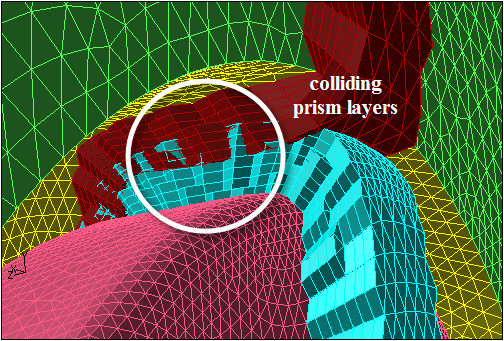
If the zones on which you want to grow prisms are very close to each other, the prism layers from zones may intersect or collide with each other. This results in bad quality of prism layers.
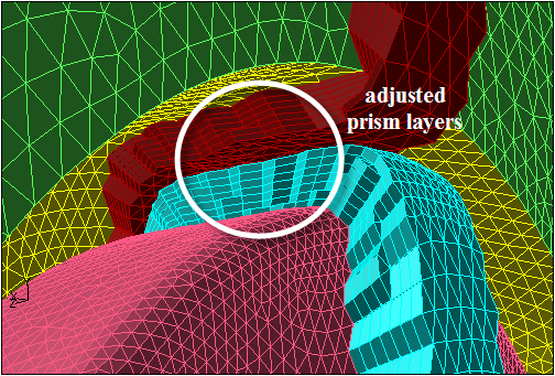
For example, in Figure 7.88: Collision of Prism Layers, the prism layers grown from proximal surfaces intersect each other. The Allow Shrinkage option allows you to avoid the intersection of prism layers by adjusting the height of the prism layers in closely placed zones. Figure 7.89: Prism Layers Shrunk to Avoid Collision shows the use of this option to avoid intersection of the prism layers by adjusting the prism layer height.
A value of n for Gap Factor implies that a gap equal to n times the maximum base edge length at the node in question will be maintained. Hence, a value of 1 implies that the gap maintained is equal to the maximum base edge length at the node considered.
Important: Offset heights are scaled only in the regions where the intersection of prism layers takes place. For the remaining regions, the prisms are created according to the specified parameters.
You can also ignore prisms in regions of close proximity during prism generation. The area of proximity will be determined based on the shrink factor specified. Prism layers will be grown from the remaining regions according to the specified parameters.
Figure 7.90: Ignoring Areas of Proximity shows a portion of the model where the region of proximity in a sharp corner has been ignored while creating prisms.
For automatic adjustment of intersecting/colliding prism layers while growing prisms, do the following:
Specify the prism growth parameters.
Click Growth Options... in the Growth tab to open the Prisms Growth Options dialog box.
Enable the appropriate options in the General Options group box.
Specify the parameters required for the proximity calculation and controlling the prism layer height.
Enable Allow Shrinkage to allow shrinkage of prism layers in areas of proximity. This option is enabled by default.
Enable Keep First Layer Offsets, if required.
This option allows you to keep the original first offset height and scale the offset heights for the remaining layers in case of intersecting prism layers.
Specify an appropriate value for Gap Factor.
Enable Allow Ignore to ignore the prism growth parameters in areas of proximity.
Enter an appropriate value for Max Aspect Ratio or Max Shrink Factor as required.
Click and close the Prism Growth Options dialog box.
Click in the Prisms dialog box.
You can generate fewer prism layers and then split them as part of the prism generation process to generate the total number of prism layers required. This option is faster than generating the same total number of prism layers.
You can specify the number of divisions per prism layer as follows:
Specify the prism growth parameters.
Click to open the Prisms Growth Options dialog box.
Enable Split in the Split Options group box.
Specify the Divisions Per Layer.
Click and close the Prism Growth Options dialog box.
Note: To create split prism layers, there should be a unique and valid prism cap face zone
(with the name *prism-cap*) associated with the prism cell
zone.
In some cases, it may be important for the prismatic mesh to be orthogonal near the original boundary. For such cases, there are two ways to preserve orthogonality:
Decrease the value specified for the Max. Angle Change in the Direction tab of the Prisms dialog box to a lower value to limit the change in normal direction in each prism layer.
This parameter is set to 60 degrees by default. This means the normal direction at a node can change up to 60 degrees during normal, edge, and node smoothing. For example, if you reduce this parameter to 10 degrees, the change in normal direction will be more gradual, and the mesh near the original boundary will be nearly orthogonal.
Specify an explicit number for Orthogonal Layers in the Direction tab of the Prisms dialog box.
When you specify orthogonal layers, you should decrease the Max Angle Change to approximately 10 degrees. This will prevent sudden sharp changes in normal direction at the first non-orthogonal layer.
For a non-orthogonal layer, edge swapping, normal, edge, or node smoothing will be performed so that the layer is orthogonal to the original boundary. For example, if you specify 5 orthogonal layers, no smoothing will be performed on the first 5 layers, resulting in direction vectors that are normal to the original surface mesh faces. Full smoothing is used on the sixth and subsequent layers.
Important: If you are preserving orthogonality near the original boundary, make sure that the prism layers do not grow too quickly. Use small layer heights, relative to the sizes of the faces on the original boundary. If prism layers grow quickly, the nearly-orthogonal direction vectors are likely to cross at sharp concave corners, causing the prism generation to fail. The prism layer generation will be stopped at this point. See Normal Smoothing.
Preserving orthogonality can affect skewness and lead to left-handed faces and/or negative volumes. See Negative Volumes/Left-Handed Faces/High Skewness for details.
The offset distance for a given node is the distance between adjacent layers at that node. This distance is based on the prism layer height computed from the specified prism growth parameters. The new node for a prism layer is placed at this distance along the direction vector.
There are four methods available for determining the offset distances:
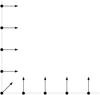
Uniform Offset Distance Method: In this method, every new node (child) is initially the same distance away from its parent node (that is, the corresponding node on the previous layer, from which the direction vector is pointing).
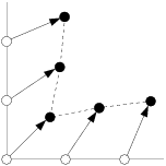
Uniform distances are fine for planar surface meshes, but they result in crevices at sharp corners, for example, the 90 degree corner in Figure 7.91: Uniform Offset Distance Method. The direction vector at the corner node will be at an angle of 45 degrees, while the vectors at the adjacent nodes will be slightly more orthogonal to their faces. For uniform distances, this places the nodes for the first layer as shown in Figure 7.91: Uniform Offset Distance Method.
The dashed line connecting the new nodes begins to pinch inward at the corner. The distances between parent and child nodes are still all the same, but the angles of the direction vectors introduce this pinching effect. Without some sort of correction such crevices can eventually collapse.
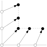
Minimum Height Offset Distance Method: In this method, child nodes are guaranteed to be at least as far from their parent nodes as the distance computed for the current layer from the growth inputs. The mesher will also try to retain the shape of the original boundary.
For a perfect 90 degree corner, this results in a perfect 90 degree corner for the next layer (see Figure 7.92: Minimum-Height Offset Distance Method). Thus, in this method the shape is better preserved if no additional smoothing is applied.
The minimum height method have some limitations. If the angle of the direction vector at the corner is not 45 degrees (that is, if it does not exactly bisect the angle between the faces), the minimum-height method can increase skewness.
Aspect Ratio Method: This method allows you to control the aspect ratio of the prism cells that are extruded from the base boundary zone. The aspect ratio is defined as the ratio of the prism base length to the prism layer height. The various growth methods (constant, linear, geometric, and exponential) can be used to specify the aspect ratio of the first layer.
When a non-constant growth method is used, the aspect ratio for subsequent layers will change accordingly. The heights of the prism cells will vary according to the local face sizes in the surface mesh, providing a convenient way to automatically vary prism heights across a zone.
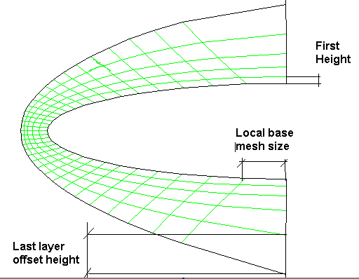
Last Ratio Method: This method also allows you to control the aspect ratio of the prism cells that are extruded from the base boundary zone. You can specify First Height for the first prism layer. If you select this method, the various growth methods will not be accessible. The last aspect ratio method is explained in Figure 7.93: Last Ratio Method.
Local base mesh size is used to find out the offset height for the last layer. For example, if you specify
80as the Last Percent value the offset height of the last layer will be 0.8 times the local base mesh size. Local growth rate is used to calculate the other intermediate offset heights exponentially.Note: Once calculated, the actual last last layer offset height is not adjusted in cases of concave or convex base, or non-orthogonal layers.
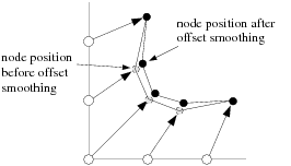
Offset Smoothing
The purpose of offset smoothing is to eliminate spikes and dips in the new surface layer. Smoothing is applied iteratively. Figure 7.94: Effect of Offset Smoothing shows how the nodes are moved during offset smoothing.
As each layer of prisms is built, the mesher needs to know the direction in which to build. There are two methods available for determining the direction vectors:
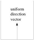
Extrusion Method: For creating straight-sided prism regions without any curvature, you can specify a uniform direction vector for all prism layers. Select Uniform in the Method list in the Direction tab of the Prisms dialog box.
Specify the uniform direction vector or click Compute in the Vector group box. This constant vector will be used for all prism layers, instead of computing a new direction for each layer (see Figure 7.95: Uniform Direction Vector for a Straight-Sided Prism Region).
Note: The Grow On Two Sided Wall option cannot be used when the Uniform method is selected.
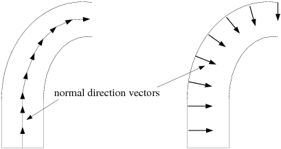
Normal Method: For regions with curvature, the appropriate normal direction vector at each node will be determined because it may be different for each node and each layer. See Figure 7.96: Normal Direction Vectors for a Curved Prism Region. Select Normal in the Method group box in the Direct tab of the Prisms dialog box.
Normal Smoothing
The normal direction vectors obtained using the methods described in Direction Vectors are smoothed so that there is a gradual change in direction from one node to the next. This will reduce the chance of direction vector intersection, which causes the prism generation to fail. This step is not necessary when a uniform direction vector is used because there is no change in direction from one node to the next.
Figure 7.97: Normal Direction Vectors Before Smoothing shows normal direction vectors in the vicinity of a sharp (90 degree) corner.
The direction vector is at an angle of 45 degree at the corner, while elsewhere it is 0 or 90 degrees. These direction vectors will intersect and prisms cannot be generated. Figure 7.98: Normal Direction Vectors After Smoothing shows the normal direction vectors near the corner after they have been smoothed. After smoothing, the normal direction changes more gradually from node to node.
It is possible to create very thin prism layers using the direction vectors shown in Figure 7.97: Normal Direction Vectors Before Smoothing, as long as the last layer lies below the point where the vectors cross.
For each zone adjacent to the zones from which you grow prisms, the angle between the prism growth direction and the adjacent zone will be checked. Depending on the size of this angle, the mesher will decide whether to use the adjacent zone for the prism sides, or create a new zone.
Using Adjacent Quadrilateral Face Zones
An adjacent zone with quadrilateral faces will be used without modification as the prism-side boundary if it satisfies the following requirements:
It must share nodes with the boundary zone from which you are building the prisms that is, there must be no free nodes (see Free and Isolated Nodes) where the zones touch.
The angle between the adjacent zone and the prism growth direction must be less than the specified threshold, Max. Adjacent Zone Angle (in the Project tab of the Prisms dialog box). The default threshold value is 75 degrees.
For example, if you are growing prisms from the bottom surface in Figure 7.99: Effect of Adjacent Zone Angle using the default maximum adjacent zone angle of 75 degrees, the zone on the left will be excluded, but the zone on the right will be used as it is. A new zone will be created for the left sides of the prisms.
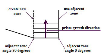
To fill in the gap on the left side of Figure 7.99: Effect of Adjacent Zone Angle, create pyramids using the prism side faces, create a domain, and generate tetrahedral cells.
Projecting to Adjacent Triangular Face Zones
If an adjacent zone has triangular faces, two additional steps will be performed to incorporate the zone into the prism layers: projection and retriangulation. The mesher will project the outer nodes of the prisms onto the triangular faces of the adjacent zone, provided it satisfies the following requirements:
It must share nodes with the boundary zone from which you are building the prisms. That is, there must be no free nodes (see Free and Isolated Nodes) where the zones touch.
The angle between the adjacent zone and the prism growth direction must be less than the specified threshold, Max. Adjacent Zone Angle (in the Project tab of the Prisms dialog box). The default threshold value is 75 degrees.
In Figure 7.99: Effect of Adjacent Zone Angle, the zone on the right will be projected to and retriangulated, while the zone on the left will be excluded.
Retriangulation
As shown in Figure 7.82: Prism Shapes, the sides of the prism will always be quadrilateral faces, regardless of the type of face from which the prism is built (triangular or quadrilateral). If the prism-side nodes are projected to an adjacent triangular boundary face zone:
The prism-side faces on the shared boundary will be overlaid on the triangular faces of the existing boundary zone.
The triangular boundary zone will be retriangulated so that the triangular portion of the zone ends at the border of the portion now filled with quadrilateral faces. This is done to obtain a conformal mesh where all the nodes match up at face edges.
The triangles that were overlapping the quadrilateral prism-side faces will be deleted.
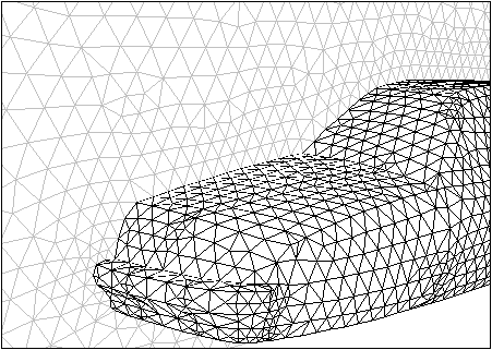
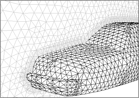
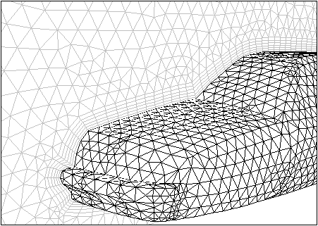
Figure 7.100: Symmetry Zone and Car Wall Before Prism Generation shows the initial boundary mesh for a car and the symmetry boundary beside it. If the prisms are generated from the car body without retriangulation of the triangular symmetry boundary, the resulting boundary mesh will be as shown in Figure 7.101: Symmetry Zone and Car Wall After Prism Generation Without Retriangulation. With retriangulation, the boundary mesh will appear as in Figure 7.102: Symmetry Zone and Car Wall After Prism Generation and Retriangulation.
You can improve prism cell quality in a postprocessing step after all the required prism layers are created. The following options are available:
The Prism Improve dialog box contains options that allow you to improve the prism cell quality based on the quality measure selected. The quality measures available are ICEM CFD quality, orthoskew, skewness, or squish. The following options are available:
The Smooth option allows optimization based smoothing of prism cells. Poor quality cells can be identified based on the quality measure selected. The nodes of cells with quality worse than the specified Max Cell Quality value will be moved to improve quality. The cell aspect ratio will also be maintained based on the value specified for
max-aspect-ratio.The Improve option collects and smooths cells in layers around poor quality cells. Poor quality cells can be identified based on the quality measure selected. Cells with quality worse than the specified Max Cell Quality value will be identified, and the nodes of the cells surrounding the poor quality cells will be moved to improve quality. The cell aspect ratio will also be maintained based on the value specified for
max-aspect-ratio.The Smooth and Improve option uses a combination of node movement and optimized smoothing to improve the quality. This option is a combination of the Smooth and Improve options. The cell aspect ratio will also be maintained based on the value specified for
max-aspect-ratio.
When the Smooth and Improve option is enabled in the Post Operations group box in the Improve tab of the Prisms dialog box, the prism cells will be improved based on the options selected in the Prism Improve dialog box, after the required prism layers are created.
You can alternatively use the options in the Prism Improve dialog box to improve the prism cell quality in a postprocessing step after the mesh is created.
> > >
In cases where the prism mesh is created separately (without using the Merge Cell Zones option in the Auto Mesh tool) and the prism-cap zone exists, you can use additional options to remove layers of poor quality cells in regions of poor quality and sharp corners.
The Prism Post Ignore dialog box contains options that allow you to remove poor quality prism cells based on quality, intersection, interior warp, and feature edges. You can specify the number of cell rings to be removed around the marked cells. Cells will be marked for removal in regions of sharp corners based on the Ignore Options selected and then extended based on the number of cell rings specified. Additional cells will be marked for removal in regions of high aspect ratio and feature angle (if selected in the Expand Ignore Options group box) around the exposed prism side.
The Feature Edges tab contains options for manipulating feature edges to be used for the post-ignore operation. You can extract edge zones from the prism base zones when the prism cap zone is selected in the Boundary Zones list. The edge zones are extracted based on the Feature Angle specified. Other operations like merging or separating the edge zones are also available.
The boundary will be smoothed at feature corners after the prism cells have been removed. The prism-side faces exposed by the removal of the prism cells will be collected in a zone named
prism-side-#, while for a zonewall-#, the faces corresponding to the ignored prism cells will be collected in a zone namedwall-#:ignore. You can also optionally smooth the prism side nodes from the base node to the cap node to create better triangles for the non-conformal interface.When the Ignore option is enabled in the Post Operations group box on the Improve tab of the Prisms dialog box, the prism cells will be removed based on the options selected in the Prism Post Ignore dialog box, after the required prism layers are created.
Note: The Feature Edge option, under Ignore Options in the Prism Post Ignore dialog box, requires a prism-cap zone to be present so it cannot be used as a Post Operation control during prism generation.
You can alternatively use the options in the Prism Post Ignore dialog box to remove layers of poor quality cells in a postprocessing step after the mesh is created.
> > >
The Prism Tet Improve Cavity dialog box contains options for creating a cavity in regions where the prism quality is adequate, but the quality of adjacent tetrahedra is poor. The cavity is created based on the tetrahedral cell zone, the quality measure and the corresponding threshold value specified. Additional cells will be removed based on the number of expand cell rings specified. You can create a cavity comprising only tetrahedral cells or optionally include prism cells when the cavity is created. When prism cells are also included in the cavity, you can specify whether the non-conformal interface is to be created.
> > >
Improving warp in prisms is a postprocessing step which is carried out after all the required prism layers are created. The face warp in the generated prism faces is improved by moving the nodes of the face to make it planar.
When the Improve Warp option is enabled in the Post Operations group box in the Improve tab of the Prisms dialog box, the prism layers having faces with warp ≥ 0.5 are identified. The nodes on the identified faces are moved and the new location of the node is updated only when:
The overall maximum warp of the faces connected to the node has decreased.
The overall maximum skewness of the cells connected to the node has decreased or remained the same.
This is useful in regions having complex sharp corners, where the nodes of a prism cell may have drastic normal change.
Scoped prism controls allow you to apply prism layer parameters to specific regions of the mesh object. Accessible through the Auto Mesh volume-meshing tool, the scoped prism process first creates boundary layers based on the defined controls, and then proceeds to generating the tet/hexcore mesh.
Important:
Volumetric regions need to be computed prior to object based volume meshing. The computing of regions includes topology checks, re-orienting of normals, and baffle identification and handling before generating the volume mesh.
The direction of prism growth does not need to be set up separately. The prism layers are always grown into the regions selected; normals are re-oriented accordingly when the regions are computed.
The scoped prisms method does not use all of the settings made in the Prisms dialog box or using the commands in the
/mesh/prismmenu. Scoped prisms are used for object based meshing and are widely used in themesh/scoped-prismmenu. Additionally, the scoped prism method is just another way to define controls on a group of zones, whereas final prism meshing ultimately takes place at the zone level.
To set up scoped prism controls, select scoped from the Grow Prisms drop-down list in the Auto Mesh dialog box and click to open the Scoped Prisms dialog box.
You use the Scope To drop down list to select fluid or solid regions.
You can select fluid-regions, solid-regions, or named-regions. If named-regions is selected, you can enter the region name (wildcards supported) in the Volume Scope field or click the button (
 ) and select the
regions in the Volume Scope dialog box.
) and select the
regions in the Volume Scope dialog box.Within the selected regions, you use the Grow On drop-down list to select the boundary type on which to grow prism layers.
You can use all-zones for unrestricted boundary type. Alternatively, use only-walls to scope prism growth by wall boundary type. To scope prisms by boundary name, use selected-labels, selected-face-zones, or solid-fluid-interface and enter the name or pattern in the Boundary Scope field, or click the Browse button (
) to use the Boundary Scope dialog box.If interior baffles exist, the Grow on both sides of baffles option will be available. You can choose to grow prisms on both sides (default) or on a single side. In case of single side, use the Color by Normal option (hot-key combination Ctrl+Shift+C and Ctrl+N) to see on what side (gray) the prisms will grow.
You use the Offset Method drop down list to select from uniform, aspect-ratio, or last-ratio as the prism offset method. The geometric growth method is used; you can specify the growth rate as appropriate.
A meaningful Name is recommended.
Important: Fluent Meshing supports multiple scoped prism controls, however only one scoped prism control can be applied to a face zone in a given region.
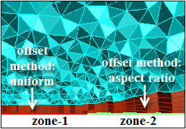
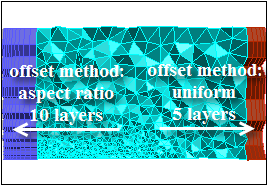
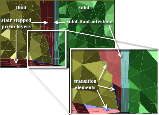
In Figure 7.103: Use of Multiple Scoped Prism Controls, prism layers are grown on adjacent zones within the fluid region, but with multiple scoped controls defined. The prism layers are stair stepped to obtain a gradual transition between the layers. Also, solid-fluid-interface is selected from the Grow On drop-down list, to enable growth of different number of layers in the solid and fluid regions.
Note:
The scoped prism controls can be read from a previously saved file (
*.pzmcontrol) or can be written to a file for further use.The command
/mesh/scoped-prisms/set-no-imprint-zonesenables you to specify boundary zones which should not be imprinted during the prism generation.
Proximity Handling
Once the initial prism layers are generated, the prism mesh is improved by a combination of optimization-based smoothing and node movement to smooth the prism cell layers. The scoped prisms approach includes two steps of collision avoidance—layer compression and stair stepping. Use the Growth Options button to setup controls to avoid collision of prism layers in proximal regions.
Enable Keep First Layer Offsets to preserve the first offset height as other layers are modified to prevent collisions.
In regions of close proximity the prism layers are first compressed to resolve gaps and sharp corners, based on the Gap Factor and Max Aspect Ratio specified.
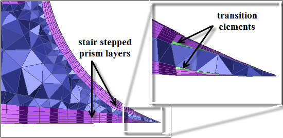
After this, cells are identified for stair stepping — a post prism meshing process carried out to avoid prism layer collision and maintain mesh quality. In areas where it is not possible to meet the quality limit specified by the Stair Stepping Threshold, or where intersections are detected, the higher prism layers will be removed and filled with pyramids and tetrahedra as transition elements between the remaining layers and the volume fill. A list of locations where the prism layers were stair stepped is printed in the console. For prism meshing, it is recommended to use ICEM CFD Quality as the quality method since it is more stringent than the Skewness metric.
If the final mesh quality is not acceptable, you can use the Auto Node Move tool with ICEM CFD quality measure to improve the mesh.
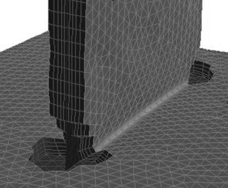
Figure 7.104: Stair Stepped Prism Layers in Sharp Corner shows an example of a sharp corner where the prism layers have been stair stepped.
This section discusses a number of common problems that you may encounter when generating prismatic meshes. An appropriate solution is also recommended for each problem. If the prism generation fails or is unsatisfactory, you may read in the mesh you saved before starting the prism generation (in step 6 of Procedure for Creating Zone-based Prisms) and repeat the process, incorporating the appropriate corrections.
The most common prism meshing problems are:
Orientation
Retriangulation failures
Too many or too few nodes, or unknown face combinations
Negative volumes, left-handed faces, or high skewness
Growing too far
Large jumps in prism height at the edges of layers
Orientation
If the faces of the boundary zone from which you are building prisms are not all oriented in the same direction, you will be alerted that the faces have been reoriented, and the prism generation process will proceed.
Retriangulation Failures
If nodes, where adjacent zones meet the zones (from which prisms are growing) are duplicated, the mesher will be unaware that the zones are connected. It will ignore such zones when considering nodes for projection, and hence retriangulation is likely to fail.
Solution: To verify this problem check the messages printed before the first prism layer. It should contain a list of all the zones connected to the zones from which you are growing the prisms.
Make sure there are no free nodes in the surface mesh before growing any prisms.
Use the Count Free Nodes button in the Merge Boundary Nodes dialog box to check for free nodes.
Enable the Free option in the Faces section of the Display Grid dialog box to see where the free nodes are located.
Too Many/Few Nodes or Unknown Face Combinations
If you receive the following type of messages, then you are most likely growing prisms into existing cells.
Warning: wedge cell c887 has too many nodes
Warning: wedge cell c1928 has too few nodes
Warning: base_mask = 7 (0x7), unknown face combinations
Either you have already grown prisms from the selected zones, or you are growing them in the wrong direction into cells on the other sides of the selected zones. In the latter case, reorient the normals and growing the layers. See step 4 in Procedure for Creating Zone-based Prisms.
Negative Volumes/Left-Handed Faces/High Skewness
The prism layer creation process will automatically stop if negative cell volumes, left-handed faces, or high skewness are detected.
Left-handed faces are faces that have collapsed into their cells. You can view them by enabling the Left Handed option in the Faces section of the Display Grid dialog box. Very high skewness occurs when the value of skewness is greater than the specified Max. Allowable Skewness in the Improve section of the Prisms dialog box). These problems can occur where prism layer fronts are advancing too quickly in areas of high curvature.
For example, the first layer height may be greater than the minimum edge length of your original surface mesh. You should compare the First Height with the results of clicking the Edge Size Limits button in the Growth section of the Prisms dialog box. The First Height should usually be smaller than the minimum edge size.
Solution: If the First Height is reasonable but you are unable to successfully generate your requested Total Height, try one of the following solutions:
Reduce the First Height or the parameter used for the growth Method (that is, Slope, Rate, or Exponent), and increase the Number of Layers. Extra layers allow smoothing to compensate better for sharp edges and corners.
If you have specified a nonzero value for Orthogonal Layers (in the Direct section of the Prisms dialog box), change it to zero. Increasing orthogonality can reduce robustness.
If you have reduced the Max. Angle Change (in the Direct section of the Prisms dialog box) from its default of 70 degrees to improve orthogonality, reset it to 70.
If you have disabled edge swapping or normal, offset, or edge smoothing, turn them back on.
If you are using the minimum-height offset method (enabled with the
mesh/controls/prism/offset-methodtext command), switch back to the uniform method.Increase the number of Layers in the Improve section of the Prisms dialog box if it is smaller than the number of layers being grown.
If you are growing simultaneously from multiple zones, use zone-specific growth controls. Use smaller initial heights and/or growth rates for zones that are having problems.
Growing Too Far
The problem here is growing too many layers. Ideally, to provide for a smooth transition to the nearly-equilateral tetrahedra, the volume of the tetrahedra should be the local growth rate times the volume of the last layer prism cells.
Solution: To ensure this does not happen, verify that the prism parameters satisfy the above condition.
Large Jumps in Prism Height
If the prisms use quadrilateral faces of adjacent zones, and the node spacings on these faces are very different from the layer heights, the prism heights jump at the outer edges.
Solution: To fix this problem,
replace the adjacent quadrilateral face zones with triangular face
zones, using the /boundary/remesh/triangulate text command. When you reattempt the prism generation, the zone will
be projected to and retriangulated.
Because the outer nodes of the prisms are projected to the adjacent boundary zone, and the original nodes on that portion of the zone are discarded, the different node spacing on the adjacent zone will not affect the prism heights at the outer edges.