


The first step in producing an unstructured mesh is to define the shape of the domain boundaries. You can create a boundary mesh in which the boundaries are defined by triangular or quadrilateral facets using a preprocessor (GAMBIT or a third-party CAD package) and then create a mesh in the meshing mode in Fluent. You can also modify the boundary mesh to improve its quality and create surface meshes on certain primitive shapes. The following sections discuss mesh quality requirements and various techniques for generating an adequate boundary mesh for numerical analysis.
- 7.6.1. Manipulating Boundary Nodes
- 7.6.2. Intersecting Boundary Zones
- 7.6.3. Modifying the Boundary Mesh
- 7.6.4. Improving Boundary Surfaces
- 7.6.5. Refining the Boundary Mesh
- 7.6.6. Creating and Modifying Features
- 7.6.7. Remeshing Boundary Zones
- 7.6.8. Faceted Stitching of Boundary Zones
- 7.6.9. Triangulating Boundary Zones
- 7.6.10. Separating Boundary Zones
- 7.6.11. Projecting Boundary Zones
- 7.6.12. Creating Groups
- 7.6.13. Manipulating Boundary Zones
- 7.6.14. Manipulating Boundary Conditions
- 7.6.15. Creating Surfaces
- 7.6.16. Removing Gaps Between Boundary Zones
- 7.6.17. Using the Loop Selection Tool
Manipulation of boundary nodes is an effective way to influence the boundary mesh quality. Operations for deleting unwanted boundary nodes can be performed in the Merge Boundary Nodes dialog box or with the associated text commands.
The mesh generation algorithm does not permit duplicate nodes; that is, two nodes that have the same Cartesian coordinates. Duplicate nodes may be created by mesh generators that preserve the node locations at adjoining edges of adjacent surfaces, but give different labels to the two sets of nodes. The nodes and edges at which these surfaces meet are termed free nodes and free edges.
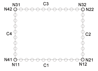
Figure 7.31: Free Nodes shows a simple geometry in which the free nodes are marked. Although the node at the end of curve C1 (N12) is located in the same position as the node at the beginning of curve C2 (N21), each is a free node because it is not connected in any way to the adjoining curve.
Though the nodes have the same location, the mesher knows only that they have different names, and not that the curves meet at this location. Similarly, a free edge is a surface edge that is used by only one boundary face. To check the location of free nodes, use the Display Grid dialog box. Free edges are acceptable when modeling a zero-thickness wall (“thin wall") in the geometry (for example, Figure 7.32: Example of a Thin Wall). Isolated nodes are nodes that are not used by any boundary faces. You can either retain these nodes to influence the generation of the interior mesh (see Inserting Isolated Nodes into a Tet Mesh), or delete them.

You can connect triangular boundary zones in the geometry using the set of intersection operations available. These can be used to resolve intersections, overlaps, and for connecting zones along the free boundaries.
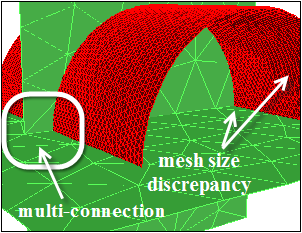
The intersect option is used to connect intersecting tri boundary zones. Figure 7.33: Intersection of Boundary Zones shows an example where the intersect option can be used. The connection is made along the curve (or line) of intersection of the boundary zones. You can use the intersection operation on multi-connected faces as well as in regions of mesh size discrepancy.
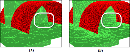
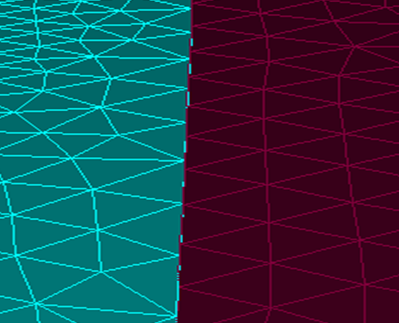
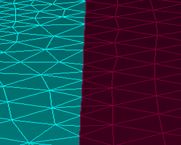
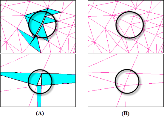
To intersect boundary zones with a gap between them, specify an appropriate Tolerance value. All zones with the distance between them less the specified tolerance value will be intersected. The tolerance can be either relative or absolute. When intersecting zones having different mesh sizes, you can use the Refine option to obtain a better graded mesh around the intersecting faces (see Figure 7.34: Intersection (A) Without and (B) With the Refine Option).
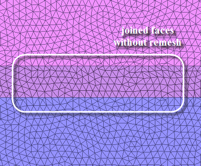
The join option is used to connect two overlapping tri boundary zones (Figure 7.35: Partially Overlapping Faces). The overlapping areas of both the boundary zones are merged and the mesh at the boundary of the region of overlap is made conformal. To join surfaces that are on top of each other but not connected (with a small gap), specify an appropriate Tolerance value. The portion of the surfaces within the tolerance value will be joined. The boundary zone selected in the Intersect Tri Zone defines the shape of the combined surface in the overlap region. The shape in the With Tri Zone may be changed to perform the join operation.
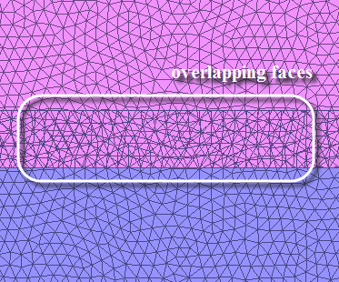
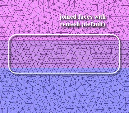
Figure 7.36: Joining of Overlapping Faces and Figure 7.37: Remeshing of Joined Faces show the overlapped faces after joining and after remeshing the joined faces.
Tip: In case of completely overlapping face zones, you may need to separate the zones and then
join individual pairs. In such cases, you may use the
/boundary/check-duplicate-geom command to delete the duplicate face
zone instead.
The stitch option is used to connect two tri boundary zones along their free edges. You cannot use this option to connect the surfaces at a location other than the free edges in the mesh. Gaps within the given tolerance are closed using nearest point projection.
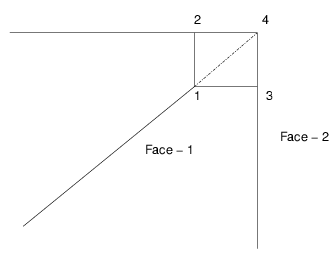
Figure 7.38: Nearest Point Projection for Stitching shows a cut through the two surfaces, Face-1 and Face-2, that are separated by a gap. The points of nearest projection will determine the location of the intersection curve. Therefore, point-1 will be connected to point-2 or point-3. All three connect operations allow a small gap (within the tolerance specified) between the intersecting boundary zones; however, the gap should not distort the shape of the geometry.
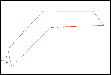
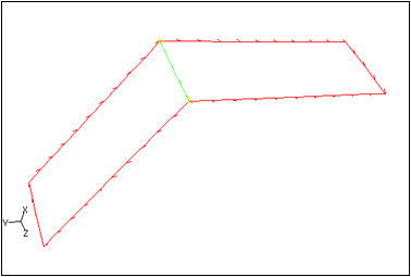
Figure 7.39: Surfaces Before Stitch and Figure 7.40: Surfaces After Stitch show the surfaces before and after the stitch operation, respectively
In general, all three connect operations calculate the intersection curve (or line) between the two surfaces to be connected. The intersection curve is constructed as follows:
Intersect constructs the curve as the intersection of two zones.
Join constructs the curve as the outer boundary of the overlapping region within the specified tolerance of the two surfaces.
Stitch constructs the curve along the free boundaries and within the specified tolerance.
The intersection curve is remeshed with a local spacing calculated from the intersecting surfaces. The intersection curve is inserted into the surfaces and will result in a retriangulation of the surfaces along the intersection curve.
The /boundary/remesh/remesh-overlapping-zones command extracts the
boundary edge zones from the zone to imprint. The intersecting curve is inserted into the zones.
During the insertion, the zones are retriangulated.
After any connect operation, remesh is called automatically. To disable the post-remesh operation, use the text command:
/boundary/remesh/controls/intersect/remesh-post-intersection?
no
To perform any of the intersection operations, do the following:
Select the boundary zones you want to intersect in the Intersect Tri Zone list.
Select the boundary zones with which you want to intersect the selected boundary zone in the With Tri Zone list.
Select the appropriate operation from the Operation list.
Specify the appropriate Tolerance value (if the surfaces have a gap between them).
Enable Absolute Tolerance, Refine, or Separate as appropriate.
Click .
The faces that will be affected by the intersection operation are highlighted. This also helps you decide whether the specified tolerance is appropriate.
Click .
You can use the Join dialog box to join overlapping face zones based on selections in the graphics window.
Select the overlapping face zones in the graphics window and click ![]() . Alternatively, use the hot-key Ctrl+T to invoke the miscellaneous tools and then Ctrl+J to open the Join dialog box.
. Alternatively, use the hot-key Ctrl+T to invoke the miscellaneous tools and then Ctrl+J to open the Join dialog box.
The detailed procedure is described in Using the Join Dialog Box.
You can use the Intersect dialog box to join overlapping face zones based on selections in the graphics window.
Select the overlapping face zones in the graphics window and click ![]() . Alternatively, use the hot-key Ctrl+T to invoke the miscellaneous tools and then Ctrl+I to open the Intersect dialog box.
. Alternatively, use the hot-key Ctrl+T to invoke the miscellaneous tools and then Ctrl+I to open the Intersect dialog box.
The detailed procedure is described in Using the Intersect Dialog Box.
Tools are available for making boundary repairs, enabling you to perform primitive operations on the boundary mesh, such as creating and deleting nodes and faces, moving nodes, swapping edges, merging and smoothing nodes, collapsing nodes, edges, and faces, splitting faces, and moving faces to another boundary zone.
This section describes the generic procedure for modifying the boundary mesh using the Modify Boundary dialog box. In addition to the Modify Boundary dialog box, you may also use the Display Grid dialog box during the modification process.
Display the boundary zones that you want to modify, using the Display Grid dialog box. If you need to modify many zones, display them one at a time to make the graphics display less cluttered.
Select the type of entity you want to select with the mouse: edge, node, position, and so on in the list in the Modify Boundary dialog box.
Select the entities you want to operate on using the mouse-probe button (a right-click, by default) in the graphics window.
You can select individual entities one at a time, or select a group of them by defining a selection region. See Controlling the Mouse Probe Function for details. The selected entities will appear in the Selections list in the Modify Boundary dialog box.
Click the appropriate button to perform the boundary modification.
The mesh is automatically re-displayed after the operation is performed, enabling you to immediately see the effect of your change.
Repeat the process to perform different operations on different entities.
Warning: Save the mesh periodically as it is not always possible to undo an operation.
You can perform the following operations using the Modify Boundary dialog box:
Creating Nodes
To create nodes, do the following:
Select the required positions (or enter node coordinates explicitly in the Enter Selection box).
Select node in the Filter list or press Ctrl+N.
Click or press F5.
Creating Faces
To create a face, do the following:
Select 3 or 4 nodes and the optional zone.
Use the hot keys Ctrl+N and Ctrl+F to select node and face as Filter, respectively.
Click or press F5.
While creating a face:
If you do not select a zone, the new face will be in the same zone as an existing face that uses one of the specified nodes.
If the nodes you use to create a face are used by faces in different zones, make sure that the new face is in the right zone.
If you create a face and it is in the wrong zone, use the rezoning feature.
Creating a Zone
To create a new zone, do the following:
Select zone in the Filter list (or Ctrl+Z).
Click or press F5. The Create Boundary Zone dialog box will open, prompting you for the zone name and type.
Specify the name and zone type as appropriate in the Create Boundary Zone dialog box.
Click . The new zone will automatically be added to the Selections list in the Modify Boundary dialog box.
Deleting a Node/Face/Zone
To delete the nodes or faces, do the following:
Select the nodes or faces or zones to be deleted.
Click or press Ctrl+W on the keyboard.
Merging Nodes
To merge nodes, do the following:
Select the two nodes to be merged.
Click or press F9.
Important: The first node selected is retained; the second node is merged onto the first node.
Tip: You can merge multiple pairs of nodes by selecting an even number of nodes, in the correct order, before clicking (or pressing F9). The first and second nodes will be merged, then the third and fourth, and so on.
Moving Nodes
To move the node to any position in the domain, do the following:
Select node in the filter list (or Ctrl+N).
Select the node you want to move.
Choose position in the filter list (or Ctrl+X).
Select the position coordinates or click the position in the graphics window to which you want to move the selected node.
Click .
To move the node by specifying the magnitude of the movement, do the following:
Select node in the filter list (or Ctrl+N).
Select the node you want to move.
Enter the magnitude by which you want to move the selected node.
Click .
Rezoning Faces
To rezone one or more faces, do the following:
Select the faces you want to move.
Select the zone to which you want the selected faces to move.
Click (or Ctrl+O). You can create a zone if you need to move faces to a new zone.
Collapsing Nodes/Edges/Faces
To collapse nodes, edges, or faces, do the following:
Select the appropriate Filter.
Select the two nodes (or edges/faces) you want to collapse.
Click (or Ctrl+^).
While collapsing:
If a pair of nodes is selected, both the nodes are moved towards each other (at the midpoint) and collapsed into a single node.
If an edge is selected, the two nodes of the edge collapse onto the midpoint of the edge and surrounding nodes are connected to the newly created node.
If a triangular face is selected, a new node is created at the centroid of the triangle and the selected triangular face gets deleted.
Note: You can also collapse multiple pairs of entities by selecting multiple entities before clicking . Ensure that an even number of entities is selected. The first and the second entity will be collapsed, then the third and the fourth, and so on.
Smoothing Nodes
To smooth nodes, do the following:
Select the nodes you want to smooth.
Click or press F6.
The node will be placed at a position computed from the average of the surrounding nodes.
Splitting Edges
To split edges, do the following:
Select the edges you want to split.
Click or press F7.
All faces sharing the edge will be split into two faces.
If you select multiple edges and they share a face, the split operation may not be completed. If the face referenced by the split operation for the second edge has already been split by the operation on the first edge, the second split operation will not be possible because the referenced face that no longer exists. If this happens, redisplay the mesh and reselect the edge that was not split. In such cases it may also be easier to split the face rather than the edge.
Splitting Faces
To split faces, do the following:
Select the faces you want to split.
Click or press F7.
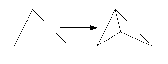
Each triangular face will be split into three faces by adding a node at the centroid. Each quadrilateral face will be split into two triangular faces.
Perform edge swapping after this step to improve the quality of the local refinement.
Swapping Edges
To swap an edge of a triangular face, do the following:
Select the edges as appropriate.
Click or press F8. If the triangular boundary face on which you perform edge swapping is the cap face of a prism layer, the swapping will automatically propagate through the prism layers.
Note: Edge swapping is not available for quadrilateral faces.
Finding Coordinates of the Centroid
To find the location of the centroid of a face or cell, do the following:
Set Filter to face or cell as appropriate.
Select the face or the cell using the mouse probe button.
Click the button (or Ctrl+L).
The face or cell centroid location will be printed in the console window.
Calculating Distance Between Entities
To compute the distance between two entities, do the following:
Set Filter to face, edge, or cell as appropriate.
Select the two entities.
Click (or Ctrl+D).
For example, if an edge (or face or cell) and a node are selected, the distance between the centroid of the edge (or face or cell) and the node is computed and printed to the console window.
Projecting Nodes
To reconstruct features in the surface mesh that were not captured in the surface mesh generation, project selected nodes onto a specified line or plane.
The Create Boundary Zone dialog box will appear automatically when you create a new face zone. You can specify the name and type of the new zone in this dialog box.
To project nodes, do the following:
Define the projection line or plane. For a projection line, select two entities and for a projection plane, select three entities. If edges, faces, or cells are selected, their centroidal locations will be used.
Click (or Ctrl+S) and the projection line or plane will be shown in the graphics display.
Select the nodes to be projected.
Click (or Ctrl+P).
The selected nodes are projected onto the projection line or plane that you defined with the operation.
Simplifying Boundary Modification
The following functions simplify the boundary modification process:
Finding the Worst/Marked Faces
You can display faces in the descending order of their quality as follows:
To find the face having the worst quality in the mesh, select Quality Limit and click or press F11.
The worst face will be displayed in the graphics window and its quality and zone ID are reported in the console.
The longest edge of the face and the node opposite it are selected, and the display is limited to the neighborhood of the highly skewed face.
If the mesh has not been displayed, the worst face, its quality, and the zone in which it lies will be reported (in the console).
Click (or the right-arrow key).
The face having the next higher quality will be displayed in the graphics window. When you subsequently click , the face having the next higher quality (after that of the previously displayed or reported face) will be displayed or reported.
Click (or the left-arrow key) to reset the display to the worst quality element.
You can also find the worst face within a subset of zones by activating a group containing the required zones using the User Defined Groups dialog box and then clicking . When you click the button after activating a particular group, the face having the next higher quality within the active group will be displayed. (Ensure that the global group is activated to have all the zones available.)
To display the marked faces in succession, do the following:
Select and click (or F11) to find the first marked face.
The face will be displayed in the graphics window.
Click (or the right-arrow key).
The next marked face is displayed in the graphics window.
Click (or the left-arrow key) to reset the display to the first marked face.
You can use the
/bounday/unmark-selected-facescommand (or Ctrl+U) to unmark the faces.
To improve the quality of the face, use the following operations:
Use the Smooth operation to smooth the node opposite the longest face.
Use the operation to collapse the shortest edge of the face, merging the other two edges together. The longer of the remaining two edges is retained, while the shorter one is merged with the other edge.
Use the Swap operation to swap the selected edge.
Use the Split operation to refine the face by bisecting the selected edge.
If the selected entities are not appropriate, clear them, choose the appropriate items, and perform the desired operations.
Deselecting a Selected Entity
If you select an inappropriate entity, you can click on it again in the graphics window to deselect it. You can also select it in the Selections list in the Modify Boundary dialog box and click . You can use F2 to deselect all entities selected.
Warning: Deselect operations are performed only on the items selected in the Selections list.
Undoing an Operation
To undo an operation, click or press F12. In some cases, a particular sequence of operations cannot be undone. Hence, make sure that you save the mesh periodically between the modifications.
Click or press F12 n times to undo the last n operations.
Warning: The Undo operation is limited to the operations in the Modify Boundary dialog box (or the /boundary/modify menu). If other operations/commands are interleaved, the Undo operation may cause unexpected results.
The Zone Remesh dialog box contains options for remeshing face zones selected in the graphics window. To remesh face zones, select them in the graphics window and press Ctrl+Shift+R to open the Zone Remesh dialog box.
Select the sizing source (size-field or constant-size).
Specify the feature angle to be preserved while remeshing the selected zones.
Specify the Constant Size value when the constant-size method is selected.
The button allows you to display size boxes to visualize the proposed constant size.
Click .
The Local Remesh dialog box contains options for remeshing marked faces or faces based on selections in the graphics window. Select the faces in the graphics window. Press Ctrl+Shift+J for face marking options. After selecting/marking the faces, press Ctrl+Shift+R to open the Local Remesh dialog box.
Set the number of radial layers of faces to be remeshed in the Rings field.
Specify the feature angle to be preserved while remeshing the selected faces.
Select the sizing source (geometric, size-field, or constant-size).
Specify the Constant Size value when the constant-size method is selected.
The button allows you to display size boxes to visualize the proposed constant size.
Click .
To specify a distance and direction for moving a node using the Move Nodes dialog box, do the following:
Select a Seed Node from your model.
Set the number of nodes to move in the Node Count box.
Set the move distance in the Move by box.
Select a direction.
Seed-Normal moves all the nodes in parallel to the seed node normal.
Local-Normal moves each node in the direction of its own normal.
Flip moves the nodes in the opposite direction.
Use Draw to preview the direction and distance selected.
You may use the Boundary Zones selection list and Boundary Zone Groups list along with Draw to isolate the zone of interest in the display.
The quality of the volume mesh is dependent on the quality of the boundary mesh from which it is generated. You can improve boundary surfaces to improve the overall mesh quality.
You can improve the boundary mesh by specifying an appropriate quality limit depending on the quality measure considered. You can also smooth and swap faces on the boundary surfaces to improve the mesh quality. You can use the Boundary Improve dialog box to improve the surfaces. You can diagnostically determine the boundary mesh quality using the Check and Skew buttons available when the Swap option is selected.
You can improve the boundary surface quality using skewness, size change, aspect ratio, or area as the quality measure.
For improving the boundary surface quality based on skewness, size change, and aspect ratio, specify the quality limit, the angle, and the number of improvement iterations. All the elements above the specified quality limit will be improved.
For improving based on the area, collapse faces and then either swap the edges or smooth the surface. All faces having area smaller than the specified minimum absolute size will be collapsed.
You can also specify the minimum relative size (size of the neighboring entity) to be considered while using the Collapse and Swap option.
Smoothing of the surface mesh allows you to control the variation in the size of the mesh elements, thereby improving the accuracy of the numerical analysis. Smoothing is critical in regions of proximity or regions where surfaces intersect and the accuracy of the approximations used in numerical analysis techniques deteriorates with rapid fluctuations in the element size. The smoothing procedure involves relocating of the mesh nodes without changing the mesh topology.
Edge swapping can be used to improve the triangular surface mesh. The procedure involves checking each pair of faces that shares an edge and identifying the connecting diagonal that results in the most appropriate configuration of faces within the resulting quadrilateral. For a face considered, if the unshared node on the other face lies within its minimal sphere, the configuration is considered to be a Delaunay violation and the edge is swapped. The procedure makes a single pass through the faces to avoid cyclic swapping of the same set of edges. Thus, the edge swapping process is repeated until no further improvement is possible. At this stage, even if a few Delaunay violations exist, the differences resulting from continual swapping are marginal.
Important: If the triangular boundary zone selected is the cap face zone of a prism layer, the edge swapping will automatically propagate though the prism layers.
To use refinement regions for local refinement in some portion of the domain (for example, to obtain a high mesh resolution in the wake of an automobile), you may refine the associated boundary zones as well. When you perform the local refinement, the boundary faces that border the refinement region will not be refined. It is therefore possible that you will have a jump in face size where a small cell touches a large boundary face. To improve the smoothness of the mesh, use the Refine Boundary Zones dialog box to appropriately refine the boundary zones that border the refinement region before performing the refinement of the volume mesh. Boundary refinement can be performed only on triangular boundary zones.
To refine boundary zones based on marked faces, do the following:
Open the Refine Boundary Zones dialog box.
> >
Select in the Options list and define the refinement region. Click the button to open the Boundary Refinement Region dialog box. Define the refinement region as appropriate.
Select the zones to be refined in the Tri Boundary Zones list.
Select the region to be refined in the Regions list. The Max Face Area will be updated based on the value specified in the Boundary Refinement Region dialog box.
Click to mark the faces to be refined.
The faces in the selected zones having face area greater than the Max Face Area specified will be marked.
Select Refine in the Options list and in the Refinement group box.
Click .
The marked faces are refined by dividing them into three faces:
To refine boundary zones based on proximity, do the following:
Open the Refine Boundary Zones dialog box.
> >
Select Refine in the Options list and Proximity in the Refinement group box.
Select the zone from which the proximity is to be determined in the Tri Boundary Zones selection list.
Specify the Relative Distance and number of refinement iterations as appropriate.
Click .
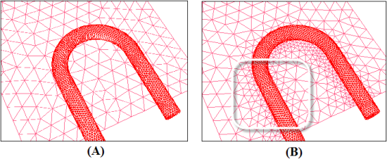
The faces in the proximity of the specified zone are refined as shown here:
To further improve the quality of the refined boundary mesh, do the following:
Select Swap in the Options list and specify the Max Angle and Max Skew as appropriate (use the Refine Boundary Zones dialog box). See Swapping for details about swapping.
Click .
If the geometry of the boundary is close to planar, you can improve the mesh quality further by selecting the Smooth option, specifying the Max Angle[5] and Relax[6] parameters, as appropriate (in the Refine Boundary Zones dialog box), and clicking .
Warning: If the geometry is far from planar, smoothing is not recommended as it may modify the shape of the boundary.
If you want to repeat the process for another refinement region, first select the Clear option and click to clear all marks.
> >
Geometric features, such as ridges, curves, or corners should be preserved while performing various operations (for example, smoothing, remeshing) on the boundary mesh. You can create edge zones for a face zone and if required, you can also modify the node distribution on the edge zone. The Feature Modify dialog box contains options available for creating and modifying edge zones. You can also draw the edge zones to determine their direction (that is, determine the start and the end points).
Important:
For object-based meshing, you can use the context menus in the tree or onscreen tools to create edge zones on selected face zones or surfaces. These options use the Fixed angle criterion. See Extract Edge Zones.
You can also use the Surface Retriangulation dialog box for creating edge zones before remeshing the face zones. The Surface Retriangulation dialog box allows you to use the face-zone approach only.
Edge zones can be created according to the specified combination of the edge zone creation approach and the angle criterion.
The angle criteria used for creating edge zones are as follows:
Fixed angle criterion
This method considers the feature angle between adjacent faces when creating edge zones. You can specify the minimum feature angle between adjacent faces as a parameter for edge zone creation. The common edge thread between two faces will be created when the feature angle is greater than the value specified.
Adaptive angle criterion
This method compares the angle at the edge with the angle at neighboring edges. If the relation between the angles matches the typical patterns of the angles in the neighborhood of the feature edge, the edge in question is considered to be a feature edge. You do not need to specify a value for the feature angle in this case.
The approaches available for edge zone creation are as follows:
Face zone approach
The edge thread is created on the entire face zone based on the specified angle criteria. The face zone approach is useful when creating edge threads on common edges where two surfaces of the zone intersect each other. The common edge is considered to be a feature edge when the angle value specified (fixed angle criterion) is less than the feature angle. Alternatively, the edge thread at the common edge can be created by detecting the change in the feature angle automatically (adaptive angle criterion).
Face seed approach
The edge thread is created surrounding the surface on which the seed face is defined based on the specified angle criteria. The common edge is considered to be a feature edge when the angle value specified (fixed angle criterion) is less than the feature angle. Alternatively, the edge thread at the common edge can be created by detecting the change in the feature angle automatically (adaptive angle criterion).
The Face Seed approach is available only when you use the Feature Modify dialog box for creating edge zones. If you use the Surface Retriangulation dialog box instead, the Face Zone approach is used for creating the edge zones.
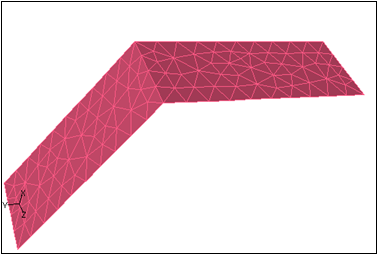
Figure 7.43: Surface Mesh - Feature Angle = 60 shows a surface mesh with two faces connected at a common edge and having a feature angle of 60 degrees. Both faces are in the same face zone.
Figure 7.44: Edge Zone for Face Zone Approach and Fixed Angle = 65 and Figure 7.47: Edge Zones for Face Seed Approach and Fixed Angle = 55 (or Adaptive Angle) show the edge zones created for different combinations of approach and angle criterion.
Figure 7.44: Edge Zone for Face Zone Approach and Fixed Angle = 65 shows the single edge zone created by using the Face Zone approach and Fixed angle criterion, with the angle specified as
65degrees. The edge thread at the common edge is not created as the specified value for Angle is greater than the feature angle.Figure 7.45: Edge Zones for Face Zone Approach and Fixed Angle = 55 (or Adaptive Angle) shows the edge zones created by using the Face Zone approach and Fixed angle criterion, with the angle specified as
55degrees. The interior edge thread at the common edge is created because the specified value for Angle is smaller than the feature angle. Alternatively, if you use the Adaptive angle criterion, the change in angle will be detected automatically and the interior edge thread will be created as shown in Figure 7.45: Edge Zones for Face Zone Approach and Fixed Angle = 55 (or Adaptive Angle).Figure 7.46: Edge Zone for Face Seed Approach and Fixed Angle = 65 shows the single edge zone created by using the Face Seed approach and Fixed angle criterion, with the angle specified as
65degrees. The edge thread at the common edge is not created because the specified value for Angle is greater than the feature angle.Figure 7.47: Edge Zones for Face Seed Approach and Fixed Angle = 55 (or Adaptive Angle) shows the edge zones created by using the Face Seed approach and Fixed angle criterion, with the angle specified as
55degrees. The boundary edge thread is created based on the seed face selected. The interior edge thread at the common edge is created because the specified value for Angle is smaller than the feature angle. Alternatively, if you use the Adaptive angle criterion, the change in angle will be detected automatically and the boundary and interior edge threads will be created as shown here:
The following edge modification options are available:
Deleting edge zones.
Copying existing edge zones (including the nodes) to a new edge zone.
Toggling the edge zone type between boundary and interior.
Grouping and ungrouping edge zones.
Orienting the edges on the edge zone to point in the same direction.
Reversing the direction of the edge zone.
Note: The direction of a boundary edge zone determines the side from which new faces are formed. The direction of a boundary edge zone should be right-handed with respect to the average normal of the face zone to be remeshed. However, the direction is not so important in the case of interior edge zones because faces are always formed on both sides of the zone.
Separating the edge zone based on the connectivity and feature angle specified.
Merging multiple edge zones into a single zone.
Note: Only edge zones of the same type (boundary or interior) can be merged.
Remeshing the edge zones to modify the node distribution.
Projecting the edges of the edge zone onto a face zone.
You can select the closest point method or specify the direction in which the edge should be projected onto the selected face zone.
Intersecting edge zones to create a new edge zone comprising the common edges.
The Feature Modify dialog box can be used for creating edge zones as follows:
Select the required zones from the Boundary Zones selection list.
Select from the Options list.
Select the appropriate option from the Approach drop-down list. Select the appropriate Seed Face when using the Face Seed approach.
Select the appropriate option from the Angle Criterion drop-down list. Specify an appropriate value for the Angle when using the Fixed angle criterion.
Enable Add Edges to Object to add the extracted edges to the object comprising the boundary face zones selected.
Click to create the edge zones.
Important:
For object-based meshing, you can use the context menus in the tree or onscreen tools to create edge zones on selected face zones or surfaces. These options use the Fixed angle criterion. See Extract Edge Zones.
You can also use the Surface Retriangulation dialog box for creating edge zones before remeshing the face zones. The Surface Retriangulation dialog box allows you to use the face-zone approach only.
The Feature Modify dialog box can be used for modifying edge loops as follows:
Operations such as deleting, copying, grouping/ungrouping, orienting, separating, and merging edge loops, toggling the edge loop type, and reversing the edge loop direction:
Select the appropriate zones in the Edge Zones selection list.
Warning: You can select only one edge zone when separating an edge zone.
Click the appropriate button in the Edge Modify group box.
Remeshing edge zones:
Select Remesh from the Options list.
Select the appropriate zones from the Edge Zones selection list.
Select an appropriate method from the Method drop-down list. You can specify a constant spacing of nodes or select either the arithmetic or the geometric method for node spacing. You can also select the Size Field option to use the size field to remesh the edge zones.
For the Constant, Arithmetic, or Geometric methods, set the following parameters:
Specify values for First Spacing and Last Spacing as required.
Note: For the Constant method, the value specified for First Spacing will be the constant node spacing. Also, the Last Spacing option is not relevant for the Constant method and will not be available.
Specify an appropriate value for Feature Angle.
Enable Quadratic Reconstruct, if required. The quadratic reconstruction option allows you to reconstruct the edge by fitting a quadratic polynomial between the original edge nodes.
Alternatively, for remeshing using the size field, make sure the size field is defined as required (see Computing the Size Field).
Click to remesh the edge zone.
Projecting edge zones:
Select Project from the Options list.
Select the appropriate zones in the Edge Zones selection list.
Select the appropriate face zone from the Face Zones selection list.
Select the appropriate projection method from the Method drop-down list. The Closest Point method specifies that the edge should be projected to the closest point on the face zone selected. The Specific Direction method allows you to project the edge on the face zone in a specific direction.
Specify the direction in which the edges should be projected when using the Specific Direction method.
Click to project the edge onto the selected face zone.
Intersecting edge zones:
Select Intersect from the Options list.
Select the appropriate zones in the Edge Zones selection list.
Enable Delete in the Overlapped Edges group box if you want to automatically delete all the overlapping edges.
You can use the
delete-overlapped-edgestext command to delete individual overlapping edges.Specify an appropriate value for Intersection Tolerance.
Click to intersect the selected edge zones.
> >
In some cases, you may need to regenerate the boundary mesh on a particular boundary face zone. You may find that the mesh resolution on the boundary is not high enough, or that you want to generate triangular faces on a boundary that currently has quadrilateral faces. Remeshing of boundary faces can be accomplished using the Surface Retriangulation dialog box.
You can remesh the boundary face zones based on edge angle, curvature, and proximity.
To remesh a face zone, you first need to create edge zones on the borders of the face zones using the parameters available in the Edge Create group box in the Surface Retriangulation dialog box (see Using the Surface Retriangulation Dialog Box).
You can create the edge zones according to your requirement by specifying an appropriate combination of the edge zone creation approach and angle criteria (refer to Creating Edge Zones for details).
Important: The Face Seed approach is available only when you use the Feature Modify dialog box for creating edge zones. Click the Feature Modify... button to open the Feature Modify dialog box.
Note:
For object-based meshing, you can create edge zones on selected face zones or surfaces using the context menus in the tree or onscreen tools. These options use the Fixed angle criterion. See Extract Edge Zones.
You can also use the Feature Modify dialog box to create new or modify existing edge zones before remeshing the face zones.
You can also draw the edge zones to determine their direction (that is, the start point and the end point).
You can modify the node distribution on the edge zones using the Feature Modify dialog box (opened using the Feature Modify... button in the Surface Retriangulation dialog box). If you want to assign different node distributions to two or more portions of an edge zone, you can separate the zone based on a specified feature angle between consecutive edges. Separation is performed automatically at multiply-connected nodes.
After creating edge zones using an appropriate combination of the edge zone creation approach and angle criteria, modify the edge zone as required. You can modify the edge zones using the options available in the Feature Modify dialog box. Refer to Using the Feature Modify Dialog Box for details on using the various options available in the Feature Modify dialog box.
It is also possible to modify the edges of the zones using the operations in the Modify Boundary dialog box. Any edges you create must have the same direction as the edge zone.
Important: You cannot remesh a continuous edge zone. You must first separate it into two or more non-continuous edge zones (that is, edge zones with start and end points).
If the mesh resolution on the boundary face zone is not enough, or you want to create triangular faces on a boundary face zone that currently has quadrilateral faces, you can remesh that boundary face zone. You can remesh the boundary face zone using the Surface Retriangulation dialog box (see Using the Surface Retriangulation Dialog Box for details).
The generalized procedure for remeshing a boundary face zone using the Surface Retriangulation dialog box is as follows:
Create the edge zones as appropriate.
Select the boundary face zone for which you want to create edge zones in the Boundary Face Zones selection list.
Select the appropriate option from the Angle Criterion drop-down list.
By default, the Face Zone approach is used to create edge zones. Therefore, you can only specify the required Angle Criterion in the Surface Retriangulation dialog box. If however, you want to use Face Seed approach, you can use the Feature Modify dialog box to create the edge zones instead (see Creating Edge Zones).
Click .
The edge zones created will now be available in the Edge Zones selection list.
Select the appropriate zones in the Edge Zones selection list and click to display them.
The selected edge zones will be displayed in the graphics window. If you are not satisfied with the edge zones and you want to modify them, open the Feature Modify dialog box.
Modify the edge zones as required using the options available in the Feature Modify dialog box. Click the Feature Modify... button to open the Feature Modify dialog box. Refer to Modifying Edge Zones for details.
When you are satisfied with the edge zones you can proceed to remesh the faces.
Select the zone to be remeshed in the Boundary Face Zones list.
You can select only a single boundary face zone for remeshing, unless the Use Conformal Remesh option is enabled.
Set the appropriate remeshing options in the Face Remesh Options group box.
Enable Size Field if you want to use the size field to remesh the faces.
Note: Edge zones associated with face zones are not remeshed implicitly. If you have feature edge zones associated with the surface being remeshed, you need to remesh them before remeshing the face zones.
Select the appropriate options from the Reconstruction (Order) drop-down list in the Face Remesh Options group box.
Enable Replace Face Zone, if required.
Important: Remeshing can be performed on both triangular and quadrilateral face zones. However, it will always result in a triangular face zone.
Enable Use Conformal Remesh if you want to conformally remesh multiple face zones connected along the shared boundary.
Note:This option is available only when Size Field is enabled and None is selected in the Reconstruction drop-down list. You will be asked to compute the size field or read a size field file.
Periodic face zones cannot be remeshed using this option.
Set the minimum Corner Angle to specify the minimum angle between feature edges that will be preserved during remeshing.
Note: The shared boundary between different zones will be remeshed only if all the face zones incident to it are selected for conformal remeshing.
Click to remesh the face zones.
Note: Edge zones are saved when the mesh file is written.
You can repair surfaces having internal cracks or free edges using the Faceted Stitch option. You can specify an appropriate tolerance value within which the free edges will be stitched. The Self Stitch only option allows you to stitch the edges within the same boundary zone. The faceted stitching operation is available only for triangular boundaries.
Figure 7.48: Mesh (A) Before and (B) After Using the Faceted Stitch Option shows the repair of a surface with internal cracks.
The command /boundary/remesh/faceted-stitch-zones enables you to perform the faceted stitching of zones.
Note: Features may not be maintained when using the faceted stitching operation.
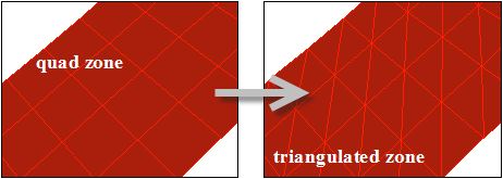
Some operations like intersection, joining, stitching, and wrapping are available only to triangular boundary zones. You can remesh a quadrilateral face zone with triangular faces as shown in Figure 7.49: Triangulating a Boundary Zone.
You can use the Triangulate Zones dialog box to perform this operation. The dialog box includes an option to either copy the quad zones and triangulate the copied zones or replace the original quad zones with the triangulated zone.
You can also use the command /boundary/remesh/triangulate to perform this operation.
There are several methods available that allow you to separate a single boundary face zone into multiple zones of the same type. If your mesh contains a zone that you want to break up into smaller portions, you can make use of these options. For example, if you created a single wall zone when generating the mesh for a duct, but you want to generate different mesh shapes on specific portions of the wall, you will need to break that wall zone into two or more wall zones.
You can use the hotkey Ctrl+Shift+S to separate faces or zones based on what has been selected. If help text display is active, a description of the face zone separation options is displayed.
If a multi-region face zone is selected, separation will be by region.
If a single-region face zone is selected, separation will be by angle. The angle may be set using the Separate Face Zones dialog box.
If a face (or edge) is selected, the face zone (edge zone) separation will be by seed.
If edge zone with face seed selection, then the face zone is separated by edge zone.
If no other selection, separation will be by marked faces.
Faces are marked using the hotkey Ctrl+Shift+J and the mouse probe/face selection filter. If help text display is active, a description of the marking options is displayed.
Ctrl+S marks individually selected faces.
Ctrl+D marks areas by flood-filling.
Ctrl+R marks areas by adding rings around the selected face.
Ctrl+Q marks faces by quality.
Ctrl+G marks faces by angle relative to the selected face, on the entire face zone.
Ctrl+L marks unmarked island faces.
Ctrl+U unmarks selected/all faces.
Ctrl+I opens a dialog box to set options for marking faces.
There are six methods available for separating a boundary face zone using the Separate Face Zones dialog box accessed via . They are:
Separating Using Angle
For geometries with sharp corners, it is often easy to separate face zones based on the significant angle. Faces with normal vectors that differ by an angle greater than or equal to the specified angle value will be placed in different zones.
For example, if the mesh consists of a cube, and all 6 sides of the cube are in a single wall zone, you would specify a significant angle of 89°. Because the normal vector for each cube side differs by 90° from the normals of its adjacent sides, each of the 6 sides will be placed in a different wall zone.
Separating Using Regions
You can also separate face zones based on contiguous regions. For example, if you want to generate the mesh in different regions of the domain using different meshing parameters, you may need to split up a boundary zone that encompasses more than one of these regions. Separating based on region splits non-contiguous boundary face zones (that is, zones that are separated into two or more isolated groups) into multiple zones.
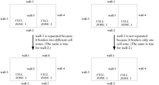
This command will also split zones that are divided by another face zone. An example could be two face zones touching in a “T". Using this command on the top zone (for example, wall-1 in Figure 7.50: Face Separation Based on Region) would split it into two zones. However, individual faces in the corners at the “T" junction may be put in their own zones. To check for this problem, list the new face zones (using the List button in the Boundary Zones dialog box), looking for zones with a single face in them. You can then merge these faces into the appropriate zone.

Separating Based on Neighboring Cell Zones
Region separation will split wall-1 in Figure 7.50: Face Separation Based on Region into two zones regardless of whether the two regions are in the same cell zone. However, neighbor-based separation will yield different results. If both regions are in the same cell zone, wall-1 will not be separated (see Figure 7.51: Face Separation Based on Cell Neighbor). If they are in different cell zones, the zone will be separated. Thus, when neighbor separation is used, wall-1 will be separated only if it is adjacent to more than one cell zone. If the two regions are in two different cell zones, then wall-1 has two different neighboring cell zones and therefore it will be separated into two wall zones.
Separating Based on the Face/Element Shape
You can also separate face zones based on the shape of the faces. For example, if a face zone contains both triangular and quadrilateral faces, you can separate the zone into two zones (one containing the triangular faces, and the other containing the quadrilateral faces).
Separating Using a Seed Element
You can separate face zones by specifying a face element (in the face zone) as a seed face. You can also separate different faces of a single face zone using this method. The surface on which you define a seed face gets separated from rest of the face zone. You can separate face zones using the seed face based on the following criteria:
Feature Angle Criteria
This method enables you to separate the surface on which you have defined a seed face from the surfaces around it based on the specified value of the feature angle. The feature angle is the angle between the normal vectors of the cells. To separate the face zones based on this criteria, do the following:
Select Seed in the Options list and Angle in the Flood Fill Options list.
Specify the seed element in the Face Seed text entry field. Right-click the face you want to choose as a seed element in the graphics window. The Face Seed field will be updated automatically.
Specify the required feature angle in the Angle field.
Click .
The surface on which you defined the seed face will be separated from other surfaces of the zone for which the feature angle change is greater than or equal to the specified value. For example, if the mesh consists of a cube, and all 6 sides of the cube are in a single wall zone, specify a significant angle of 89° and specify a seed face on any one of the walls. Because the normal vector for each cube side differs by 90° from the normals of its adjacent sides, the face on which you have defined a seed cell will be placed in a different wall zone. Therefore, two zones will be created, one zone will have a face on which you defined a seed face and the second zone will have remaining faces.
Edge Zone Criteria
This method enables you to separate the surface, on which you have defined a seed face, from the other faces in the zone based on the existing edge zones associated with it. You must create the edge zones for the given mesh to use this method.
To separate the face zones based on this criteria, do the following:
Select Seed in the Options list and Edge Loop in the Flood Fill Options list.
Specify the seed element in the Face Seed text entry field.
For this method, you will only specify the seed element. The Angle field will not be available.
Click .
Important: Create edge threads on the surface zones again using the Surface Retriangulation dialog box after performing above operations.
Separating Based on Marked Faces
You can separate face zones by placing marked faces in a new zone. To use this option in the Separate Face Zones dialog box, explicitly define a subregion of the domain (using the Boundary Refinement Region dialog box), then separate face zones based on whether or not each face in the specified zone is in the selected local region.
Another mesh refinement method involves projecting the nodes of one face zone onto another (possibly non-planar) face zone to create a new face zone that has the same connectivity as the original face zone. This new face zone is created after the projection, and no cell zones are created. The face zone that is projected is not modified in any way.
Projecting a face zone is used mainly to fill in gaps by extending the domain through the projection. The original connectivity is maintained after the projection, with the effect being that elements on the connected side zones will be stretched to cover the projection distance. Affected side zones should then be remeshed to obtain regular size elements on them. Such a remeshing results in a new side zone, after which you can (and should) delete the original side zone. Finally, you can mesh the domain to get the volume elements.
You can create groups of faces and edges that will be available in all the dialog boxes along with the default groups (for example, boundary, tri, quad, and so on). The face and edge zones are grouped separately. The User Defined Groups dialog box enables you to define new face and/or edge groups, update existing groups, activate or delete a particular group. Although the dialog box is opened from the Boundary menu, it can be used with all dialog boxes that contain zone lists.
Note: When a user-defined group is activated, the wild-cards used for zone selection in all the text commands will return zones contained in the active group. For example, the command /display/boundary-grid * will display all the boundary zones contained in the active group.
For object based meshing (see Object-Based Surface Meshing), you can create a face group and an edge group comprising the face zones and edge zones included in the specified objects using the options in the Zone Group group box in the Operations tab in the Manage Objects dialog box. Additionally, a face zone group is automatically created when a mesh object is created using the Sew operation. This face zone group is prefixed by _mesh_group, and enables easy selection of mesh object face zones for various operations (improve, smooth, and so on).
For CutCell meshing, the mesher separates the face zones by cell neighbor and creates a face zone group for the face zones of each fluid cell zone. See Generating the CutCell Mesh for details.
Note: When an object is deleted along with the face and edge zones comprising the object, the corresponding groups will also be deleted.
Boundary zones are groups of boundary faces. Usually the grouping collects boundary faces with the same boundary conditions, but further sub-groupings are often used to preserve a sharp edge in the surface mesh or simply as an artifact of the boundary mesh generation process.
Each zone has a unique ID, which must be a positive integer. You can use the options in the Manage Face Zones dialog box to manipulate the face zones. find information about each zone, identify them, merge zones or delete them, change the boundary type of all faces in a zone, rename zones, and rotate, scale, or translate zones.
Click to obtain information about the selected face zones. The zone ID, name, boundary type, and number of faces by type (tri or quad) will be reported.
Use the Change Type option to change the boundary type of the selected face zones.
Note: When changing the boundary type of any zone to type
interior, ensure that there is a single cell zone across theinteriorboundary. Retaining multiple cell zones across aninteriorboundary can cause undesirable results with further tet meshing or smoothing operations.Also, face zones having no/one neighboring cell zone should not be changed to type
interior.The mesh check will issue a warning if multiple cell zones are maintained across an
interiorboundary. The boundary type in such cases should be set tointernalinstead.Use the Copy option to copy the nodes and faces of the selected face zones.
Use the Delete option to delete the selected face zones. You can optionally delete the nodes of the face zones as well (enabled by default).
Use the Merge option to merge the selected face zones based on Alphabetical Order (default) or Larger Area.
Use the Rename option to rename the selected face zones. You can optionally change the zone name prefix as well.
Note: The zone name can have a maximum of 256 characters.
Use the Flip Normals option to flip the direction of all face normals on the selected face zones.
Use the Orient option to consistently orient the face normals on the selected face zones.
Use the Rotate option to rotate all nodes of the selected face zones through the angle specified. Enter the pivot and axis of rotation or use the option to select six nodes or positions to define the pivot and axis instead. You can optionally create a copy instead of replacing the original zones.
Use the Scale option to scale all nodes of the selected face zones by the scale factors specified. You can optionally create a copy instead of replacing the original zones.
Use the Translate option to translate all nodes of the selected face zones by the translation offsets specified. Use the option to select two nodes or positions to define the translation vector instead. You can optionally create a copy instead of replacing the original zones.
The hotkey Ctrl+Shift+N opens the Change Zone Properties dialog box which enables you to quickly rename the selected zone, set the boundary type, and set the geometry recovery option (low or high).
Note: When changing the boundary type of any zone to type interior,
ensure that there is a single cell zone across the interior boundary.
Retaining multiple cell zones across an interior boundary can cause
undesirable results with further tet meshing or smoothing operations.
Also, face zones having no/one neighboring cell zone should not be changed to type
interior.
The mesh check will issue a warning if multiple cell zones are maintained across an
interior boundary. The boundary type in such cases should be set to
internal instead.
Case files read in the meshing mode also contain the boundary and cell zone conditions along with the mesh information. The Boundary Conditions dialog box enables you to copy or clear boundary conditions assigned to the boundary zones when a case file is read.
You can copy the boundary conditions from the zone selected in the With list to those selected in the Without list using the Copy option.
You can clear the boundary conditions assigned to the zones selected in the With list using the Clear option.
You can create specific types of surfaces within the existing geometry using one of the options available in the Boundary/Create menu.
The Construct Geometry tool (![]() ) also enables you to create a bounding box or cylinder/frustum for selected or all zones displayed in the graphics window.
) also enables you to create a bounding box or cylinder/frustum for selected or all zones displayed in the graphics window.
The following sections explain how to create surfaces.
In some cases, you may want to create a box that encloses the input geometry (for example, creating a wind tunnel around the geometry). You can create a bounding box around the input geometry or only the selected zones of the geometry using the Bounding Box dialog box, or the Construct Geometry tool. You can also specify the required clearance values of the bounding box from the boundaries of the geometry.
There are two methods available for creating bounding box:
This method enables you to create the bounding box by specifying the minimum and maximum extents of the bounding box in X, Y, and Z directions.
This method enables you to create the bounding box by specifying the relative coordinate values with reference to the selected face zone.
The procedure for creating a bounding box is as follows:
Select the zones around which you want to create a bounding box in the Face Zones list.
Select the appropriate method in the Method list.
For the Absolute method, specify the bounding box extents (X Min, X Max, Y Min, Y Max, Z Min, and Z Max). If you click , the extents will be computed such that the bounding box encloses the selected boundary zones.
For the Relative method, specify the clearance values in the Delta entry fields (Delta X Min, Delta X Max, Delta Y Min, Delta Y Max, Delta Z Min, and Delta Z Max).
Initially, all the Delta entry fields will be set to
0. This implies that the bounding box will touch the boundaries of the selected face zones. Positive delta values indicate that the bounding box will be created outside the initial bounding box while negative values indicate that the bounding box will be created inside the initial bounding box.
Specify an appropriate value for Edge Length. When you click for the Absolute method, the value will be automatically set to 1/10th that of the minimum length of the bounding box.
Enable Create Object if you need to create a geometry object based on the bounding box face zone created.
Note: Do not use the Create Object option if the box is to be used as a body of influence while setting up the size functions.
Click to visualize the bounding box.
Click to create a bounding box based on the specified parameters.
The Construct Geometry tool (![]() ) enables you to create a bounding box for selected or all zones displayed in the graphics window. The bounding box extents are computed based on the entities selected or displayed and are indicated in the graphics window.
) enables you to create a bounding box for selected or all zones displayed in the graphics window. The bounding box extents are computed based on the entities selected or displayed and are indicated in the graphics window.
Select the zones (if required) and click the Bounding Box tool (
 ) to preview the bounding box extents. The bounding box is always created in the global X-Y-Z axes.
The bounding box extents can be altered interactively by selecting the direction and dragging the mouse to change the box dimensions. Click the yellow dot on the bounding box surface to select the direction.
Click Create (
 ) to open the Create Object dialog box.
Enter an appropriate Object Name.
Specify the mesh size for the surface mesh. By default, the edge length is computed as one fifth of the smallest side. Alternatively, enable Specify Sizing and specify the size to be used. Click to visualize the size set.
Click to create the bounding box. A geometry object comprising the bounding box face zones will be created.
In some cases, you may need to create a plane surface mesh in the geometry (for example, creating a baffle-like surface inside a hollow tube). You can create a plane surface and mesh the surface using triangular faces of the required size using the Plane Surface dialog box.
Warning: It is possible to create a planar surface only of rectangular shape; you cannot create a planar surface of any other shape.
There are two methods available for creating planar surface mesh:
Axis Direction Method:
This method enables you to create the plane surface perpendicular to any of the coordinate axes. Select the axis perpendicular to which you want to create a planar surface mesh and then, specify the coordinates of the points that will form a rectangular surface perpendicular to the axis selected. You can also create a plane surface enclosing the boundaries of the selected face zone using this method.
Planar Points Method:
This method enables you to create a plane surface mesh from three points in the geometry selected using the mouse.
The concept of the planar points method is shown in Figure 7.52: Planar Points Method. After specifying the planar points, the first point (P1) and second point (P2) are connected to each other by a line (line-1). Another line (line-2) is drawn through the third point (P3) parallel to the first line. Perpendiculars are drawn from points P1 and P3 on line-2 and line-1 respectively.
This creates a rectangular surface that you can mesh as required.

The procedure for creating a surface mesh is as follows:
Select the appropriate method in the Options list.
For the Axis Direction method, select the appropriate face zones, direction, and specify the coordinates of the points perpendicular to the axis.
If you select X Axis then the entry box for specifying coordinates in X direction will not be accessible. This applies to the other two axes as well.
For the Points method, specify the coordinates for the three points defining the plane. You can click the Select Points... button and select the points using the mouse button.
Specify an appropriate value for Edge Length. If you click , the Edge Length will be computed as 1/10th of the minimum distance along the coordinate axes.
Enable Create Object if you need to create a geometry object based on the plane surface face zone created.
Click to visualize the surface.
Click to create the planar surface.
In some cases, you may want to create a cylinder or frustum within the existing geometry (for example, creating an MRF zone for problems involving moving parts such as rotating blades or impellers, creating a cylindrical surface to close a gap in the geometry, and so on). You can create a cylindrical surface and mesh it with a triangular surface mesh using the options available in the Cylinder dialog box, or the Construct Geometry tool.
Using 3 Arc Nodes: You can create a cylindrical surface using three nodes that lie on a circular arc (see Figure 7.53: Cylinder Defined by 3 Arc Nodes, Radial Gap, and Axial Delta). Specify the radial gap and taper angle that will determine the actual radii of the cylinder/frustum to be created. You can specify a positive or negative radial gap value depending on the required size of the cylinder/frustum. A taper angle of zero will result in a cylinder. The axial delta values determine the axial length of the cylinder/frustum. The Caps option enables you to create the circular capping surfaces along with the cylindrical surface.
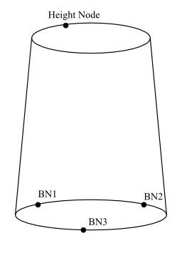
Using 3 Arc Nodes and a Height Node: You can create a cylindrical surface using three nodes which lie on a circular arc, and a fourth node to determine the height of the cylinder/frustum (see Figure 7.54: Cylinder Defined by 3 Arc Nodes and a Height Node). The radii, height, and taper angle will be determined based on the nodes selected.
Note: A planar annular surface will be created if the four nodes selected are in the same plane (that is, the height is zero).
The Caps option enables you to create the circular capping surfaces along with the cylindrical surface.
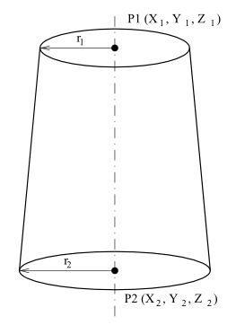
Using 2 Axis Locations or 2 Axis Nodes: You can also create a cylindrical surface by specifying the radii (r1, r2) of the cylinder/frustum and two points (P1 and P2) defining the axis (see Figure 7.55: Cylinder Defined by Axial Points and Radii). Equal values of r1 and r2 will result in a cylinder. The axis can be defined by specifying the location (X, Y, Z) of the points or by specifying the appropriate boundary nodes corresponding to the axial points P1 and P2. The Caps option enables you to create the circular capping surfaces along with the cylindrical surface.

The procedure for creating a cylindrical surface is as follows:
Select the appropriate option for defining the cylinder.
For the 3 Arc Nodes method, select the nodes on the circular arc. Enter appropriate values for Axial Delta 1, Axial Delta 2, Taper Angle, and Radial Gap.
For the 3 Arc, 1 Height Node method, select the 3 nodes on the circular arc and the height node.
For the 2 Axis Locations and 2 Axis Nodes methods, specify the points defining the axis. You can specify the locations (or node IDs) manually. Alternatively, you can click the Select Points... (or the Select Nodes...) button and select the points using the mouse. Enter appropriate values for Radius1 and Radius2.
Enter an appropriate value for Edge Length.
Enable Caps to create the circular capping surfaces along with the cylindrical surface.
Enable Create Object if you need to create a geometry object based on the cylinder/frustum face zones created.
Note: Do not use the Create Object option if the cylinder/frustum is to be used as a body of influence while setting up the size functions.
Click to preview the cylinder to be created.
When you are satisfied with the settings, click to create the cylindrical surface. Enter an appropriate zone name prefix in the Object/Zone Prefix dialog box and click .
The Construct Geometry tool (![]() ) enables you to create a cylinder/frustum based on selections in the graphics window. The cylinder/frustum dimensions are computed based on the entities selected or displayed and are indicated in the graphics window.
) enables you to create a cylinder/frustum based on selections in the graphics window. The cylinder/frustum dimensions are computed based on the entities selected or displayed and are indicated in the graphics window.
Select the entities and click the Cylinder tool (
 ) to preview the cylinder extents. Alternatively, click the Frustum tool (
  ) to preview the frustum extents.
When no selections are made, the cylinder/frustum is aligned along the global Z-axis. The default height and radius are computed based on the bounding box dimensions for the entities displayed.
When face zones are selected, the cylinder/frustum is aligned along the global Z- axis. If any two dimensions of the bounding box for the selected zones are the same, the cylinder/frustum will be aligned along the third (remaining) direction. The default height and radius are computed based on the bounding box dimensions for the zones selected.
When a single node is selected, it is used as an axis node. The cylinder/frustum will be aligned along the global Z- axis. The default radius and height are equal and computed as one-tenth the length of the diagonal of the bounding box for the displayed zones. If no zones are displayed, a value one-tenth the length of the diagonal of the global bounding box will be used.
When two nodes are selected, the mid-point of the line joining the two is used as an axis node and the cylinder/frustum will be aligned along the global Z-axis. If the nodes selected are aligned in the Z-axis, the cylinder/frustum will be aligned along the global Y-axis instead. The default radius and height are equal, and computed as half the distance between the selected nodes.
When three nodes are selected, the cylinder/frustum base circle passes through the selected nodes. The axial direction is determined by the right hand thumb rule. The default radius and height are equal. The radius is determined by the nodes selected.
When four nodes are selected, the first three are used to determine the cylinder/frustum base circle. The fourth node is used to determine the height. The radius is determined by the first three nodes selected.
The cylinder dimensions can be altered interactively by selecting the direction and dragging the mouse to change the dimensions. Click the yellow dot on the cylinder surface to change the height.
The frustum dimensions can be altered interactively by selecting the direction and dragging the mouse to change the dimensions. Click the yellow dot on either surface to change the radii and height.
Click Create (
) to open the Create Object dialog box. Enter an appropriate Object Name.
Specify the mesh size for the surface mesh. By default, the edge length is computed as one-seventh the average radius or height, whichever is smaller. Alternatively, enable Specify Sizing and specify the size to be used. Click to visualize the size set.
The Caps option enables you to create the circular capping surfaces along with the cylindrical surface. Disable this option to obtain only the cylindrical surface.
Click to create the cylinder/frustum. A geometry object comprising the cylinder/frustum face zones will be created.
In some cases, you may want to create a swept surface by projecting an edge zone along a specified linear distance in a specified direction. You can create a swept surface using the options available in the Swept Surface dialog box.
The procedure for creating a swept surface is as follows:
Create the edge zone for the swept surface.
Use the interactive edge zone creation tool to extract edge zones from existing face zones or surfaces. See Extract Edge Zones for details.
Use the Loop Selection tool to create an edge zone from selected nodes or points. See Using the Loop Selection Tool for details.
Use edge zone creation and modification options available in the Manage Objects, Feature Modify, or Surface Retriangularization dialog boxes. See Object Manipulation Operations, Using the Feature Modify Dialog Box, or Using the Surface Retriangulation Dialog Box respectively.
Open the Swept Surface dialog box.
> >
Select the edge zone to be swept from the Edge Zones drop-down list.
Select the corresponding faces from the Face Zones selection list.
Specify the distance along which the edge is to be swept in the Total Distance field.
Specify the appropriate value in the No. of Offsets field.
Specify the Vector defining the direction in which the edge is to be swept.
Alternatively, you can click and select two nodes or positions to specify the vector. The Total Distance is also computed based on the nodes/positions selected.
Enable Split Quad Faces, if required.
Enable Create Object if you need to create a geometry object based on the swept surface face zone created.
Click to create the swept surface.
In some cases, you may want to create a revolved surface from specific edge zones. The revolved surface is created by revolving the selected edge zones through the angle specified using the pivot and axis of rotation defined. You can create a revolved surface using the options available in the Revolved Surface dialog box.
The procedure for creating a revolved surface is as follows:
Create the edge zones to be used for creating the revolved surface.
Use the interactive edge zone creation tool to extract edge zones from existing face zones or surfaces. See Extract Edge Zones for details.
Use the Loop Selection tool to create an edge zone from selected nodes or points. See Using the Loop Selection Tool for details.
Use edge zone creation and modification options available in the Manage Objects, Feature Modify, or Surface Retriangularization dialog boxes. See Object Manipulation Operations, Using the Feature Modify Dialog Box, or Using the Surface Retriangulation Dialog Box respectively.
Open the Revolved Surface dialog box.
> >
Select the edges to be revolved from the Edge Zones selection list.
Specify the appropriate value in the Number of Segments field.
Specify the angle through which the edge is to be revolved in the Angle field.
Specify an appropriate value for Scale Factor depending on the radius required for the revolved surface.
Specify the pivot point and the axis of revolution. Click and select 1-6 nodes to define the pivot and axis as follows:
If only 1 node is selected, the pivot point is at the node location and the axis of rotation is the global z-axis.
For 2 nodes, the pivot point is at the midpoint of the nodes selected and the axis of rotation is the global z-axis.
For 3 nodes, the pivot point is at the first node selected. The axis of rotation is the local z-axis normal to the plane defined by the three points, the positive direction is determined by the right-hand rule.
For 4, 5 or 6 nodes, the first 3 points define a circle. The pivot point is at the center of the circle. The axis of rotation is the local z-axis normal to the circular plane, the positive direction is determined by the right-hand rule.
Enable Create Object if you need to create a geometry object based on the revolved surface face zone created.
Click to create the revolved surface.
Use the Make Periodic Boundaries dialog box to Create or Recover the periodic relationship between leader and shadow face zones in a single mesh object. The periodic boundaries are identical and contain either face or node correspondence information.
The Make Periodic Boundaries dialog box is accessible using the context sensitive menu under any mesh object or using the > > menu.
Create Periodic Boundaries
You can Create new periodic boundaries using the following procedure.
In the preprocessor, create only one of the boundaries which is to be made periodic. The to-be-periodic boundary may have multiple face zones, but should be any non-periodic boundary type.
In the Make Periodic Boundaries dialog box in Fluent meshing, select the boundary zone(s) from the Boundary Zones list. You can also select the zone(s) graphically; the names will be highlighted in the Boundary Zones list.
Enter, or check for accuracy, the periodicity information (angle, pivot and axis for rotational periodicity; shift vector for translational periodicity) in the Make Periodic Boundaries dialog box.
Periodicity information may be defined graphically (see below) or using the context-sensitive menu under Model in the Outline View, or read in with the mesh file.
Click Create.
A corresponding periodic shadow boundary will be added to the object. A zone type of periodic will be assigned to both the periodic and the periodic-shadow zones, and the face/node correspondence will be generated.
Important:
This is the only way to create periodic boundaries in the meshing mode; it is not sufficient to simply set a zone type to be periodic.
Periodicity information will be stored with the mesh data and will be extracted when the mesh file is read. Multiple periodicities may be created, but only the first is read automatically with the mesh data.
To define periodicity information by other means, follow these steps.
For rotational periodicity, the pivot point and axis of rotation can be defined graphically by selecting 1-6 nodes as follows, and then clicking Define.
If only 1 node is selected, the pivot point is at the node location and the axis of rotation is the global z-axis.
For 2 nodes, the pivot point is at the midpoint of the nodes selected and the axis of rotation is the global z-axis.
For 3 nodes, the pivot point is at the first node selected. The axis of rotation is the local z-axis normal to the plane defined by the three points, the positive direction is determined by the right-hand rule.
For 4, 5 or 6 nodes, the first 3 points define a circle. The pivot point is at the center of the circle. The axis of rotation is the local z-axis normal to the circular plane. The x-axis (0°) is defined by the 4th, 5th and 6th points and the positive direction is determined by the right-hand rule.
For translational periodicity, the shift vector can be defined graphically clicking Define and then selecting two nodes.
Rotational periodicity information may be set using the Periodicity dialog box accessed by right clicking on Model in the Outline View.
Rotational periodicity information may be set using the text command
boundary/set-periodicity.
When the periodic-shadow boundary is created from the original (periodic) boundary, the nodes around the outer edges of the shadow zone will be duplicates of existing nodes. These duplicates will be marked as free, so they can be verified by counting them and drawing them. Before generating the initial mesh, you must merge these nodes.
Important: To ensure that the periodic-shadow boundary creation works properly, you must define the node distribution correctly in the preprocessor that generates the boundary mesh.
Ensure that the distribution of nodes on the boundaries that will be shared by the shadow zone and the surfaces adjacent to it is the same as the distribution on the boundaries shared by the original (periodic) zone and its adjacent surfaces.
Note: Files created prior to Release 15 written in mesher mode are automatically converted when read into mesher mode. These files may not contain sufficient information to properly set up periodic information in case of multiple periodic pairs.
Recover Periodic Boundaries
You can Recover periodic boundaries if it exists from a mesh file using the following procedure.
Read the mesh file.
In the Make Periodic Boundaries dialog box in Fluent meshing, select the periodic boundary zone(s) from the Boundary Zones list.
Tip: You can also select the zone(s) graphically, and the names will be highlighted in the Boundary Zones list.
If it exists, periodic information (angle, pivot, and origin) will be extracted from the mesh file when it is read and will appear in the Periodicity dialog box. Alternatively, you can manually enter periodic information as described above.
Click Recover.
The Recover feature will check for any existing face zone(s) at the periodic shadow boundary. If a shadow face zone is more complex than the corresponding leader, the recover operation will fail for that zone and a warning will appear in the console. You may be able to recover the periodic boundary by reversing the angle and selecting the more complex face zone(s).
Note:
Recover first creates the periodic shadow boundary and then removes any duplicate face zone(s) at the periodic shadow boundary.
Periodic boundary recovery may be initiated using the text command
boundary/recover-periodic-surfaces.
Use the Remove Boundary Gaps dialog box to remove gaps between boundary zones.
Select the target zone in the graphics window. Click
 to set the target zone.
Select the zones for the gap removal operation and click
 to open the Remove Boundary
Gaps dialog box. Alternatively, select the zones and use the hot-key Ctrl+K.
to open the Remove Boundary
Gaps dialog box. Alternatively, select the zones and use the hot-key Ctrl+K.Specify an appropriate value for the Min. Gap Distance, Max. Gap Distance, and Percentage Margin.
Specify an appropriate value for Critical Angle. The critical angle is the maximum angle between the faces constituting the gap to be removed.
Click to see the faces marked for projection.
Click to remove the gaps between the objects selected.
The loop selection tool can be accessed by clicking ![]() in the graphics window or using the hot-key Ctrl+Shift+L. This tool provides options for creating an open or closed loop of nodes. You can create an edge zone or capping surface based on the loop selected. You can also select positions instead of nodes to define the loop.
in the graphics window or using the hot-key Ctrl+Shift+L. This tool provides options for creating an open or closed loop of nodes. You can create an edge zone or capping surface based on the loop selected. You can also select positions instead of nodes to define the loop.

The following selection options are available:
In the first group of tools, choose how the path between selected nodes/positions is defined - by edges, feature, boundary, or direct path. Click
 to switch between selecting nodes or positions to define the loop.
The second group of icons is used to select open or closed loop. Then, for closed loop mode, you can choose how the path between the first and last nodes is defined - by edges, feature, boundary, or direct path.
Creating a Capping Surface
After making the necessary selections, click ![]() (hot-key Ctrl+K) in the Loop Selection mode to open the Create Cap dialog box. The Create Cap dialog box contains options for object/zone granularity and type and for remeshing the capping surface.
(hot-key Ctrl+K) in the Loop Selection mode to open the Create Cap dialog box. The Create Cap dialog box contains options for object/zone granularity and type and for remeshing the capping surface.
Specify the object/zone granularity.
Select New Object to create a new object for the face zones. Specify the object name and a label name. If the label name is not specified, the object name will be used as the label name. Face zone names will be the same as the label names. Select the Object Type and Zone Type from the lists.
Select Add to Object to add the face zones to an existing object. Select the object and specify a label name. If the label name is not specified, the default name patch:# (# indicates the ID) will be used. Face zone names will be the same as the label names. Select the Zone Type from the list.
Select Add to Unreferenced to create unreferenced face zones. Select the Zone Type from the list. The default name patch:# (# indicates the ID) will be used for the zone name. These zones will be available in the Unreferenced branch of the tree.
Enable Remesh to remesh the capping surface created.
Click in the Create Cap dialog box.
Creating an Edge Zone
After making the necessary selections, click ![]() (hot-key Ctrl+L) in the Loop Selection mode to open the Create Edge Zones dialog box. The Create Edge Zones dialog box enables you to add the edge zone to an existing object or create an unreferenced edge zone.
(hot-key Ctrl+L) in the Loop Selection mode to open the Create Edge Zones dialog box. The Create Edge Zones dialog box enables you to add the edge zone to an existing object or create an unreferenced edge zone.
Selecting all Nodes
After making the necessary selections, click ![]() (hot-key Ctrl+J) in the Loop Selection mode to select all the nodes on the loop. These selections can then be used for operations such as collapsing, merging, or smoothing nodes.
(hot-key Ctrl+J) in the Loop Selection mode to select all the nodes on the loop. These selections can then be used for operations such as collapsing, merging, or smoothing nodes.
For the list of hot-keys associated with the options in the Loop Selection toolbar, refer to Appendix C: Shortcut Keys.
[5] Max Angle specifies the maximum angle between two adjacent face normals. When the Swap option is active, only faces with an angle below this value will be swapped. This restriction prevents the loss of sharp edges in the geometry. The valid range of entries is 0 to 180° and the default is 10°. The larger the angle, the greater the chance that a face swap will occur that may have an impact on the flow solution.
[6] Relax specifies the relaxation factor by which the computed change in node position should by multiplied before the node is moved. A value of zero results in no node movement, and a value of 1 results in movement equivalent to the entire computed increment.