


Geometries migrated from various CAD packages often contain gaps and overlaps between the surfaces due to algorithm and tolerance differences of the CAD packages. Repairing such geometries manually is a tedious and time-consuming process. Wrapping provides the ability to create reliable meshes for such geometries without extensive manual clean up and reduces the time required for preprocessing.
The object wrapping operation:
extracts a conformal, well connected mesh object on the relevant surfaces of the objects selected.
can repair gaps and overlaps in the model at the expense of a user-specified degree of geometry details.
can handle unclean geometries and does not require a watertight representation of the geometry.
can be used for defeaturing or when you need to walk over features.
The wrapper is useful in the following industrial applications:
Automotive
Underhood thermal management (engine only, front car, full car)
Cabin HVAC
External aerodynamics
Brake cooling and engine cooling
Aerospace
Engine core compartment
Cockpit HVAC, cabin HVAC
Landing gear
Drill bit applications
Smoke and fire spread
Biomedical applications
Other applications with bad input geometries
The wrapping operation uses an appropriate material point to identify the relevant surfaces of the selected objects. A well-connected mesh object is created.
The general procedure for creating a wrapper surface is as follows:
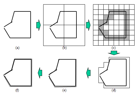
A coarse Cartesian grid is overlaid on the selected objects (including gaps and overlaps) to create a contiguous region. This Cartesian grid is used to automatically clean the input geometry and to create the water-tight representation.
The Cartesian grid is then refined based on the size functions to better represent the selected objects.
The intersection between the Cartesian grid and the input geometry is calculated and the intersecting cells are identified and marked.
The interface is extracted on the boundary of the non-intersecting Cartesian volume region that encloses the material point. A watertight, faceted representation is created along the boundary of the intersecting cells.
The nodes on this faceted representation are projected onto the faces and feature edges of the input geometry which then results in a wrapper surface closely representing the input geometry. The edges are imprinted on the wrapped zones, and individual zones are recovered and rezoned based on the original geometry object(s).
The wrapper surface quality is improved by post-wrapping operations such as smoothing, swapping, and so on. Degenerate and island edges are deleted, and intersected and remeshed as appropriate. Surfaces are remeshed based on size functions/size field.
Figure 7.57: Schematic Representation of Wrapping Process is a simple illustration of these steps.
Note:
If the global minimum size specified cannot be resolved, an error will be reported. Set up appropriate sizes and compute the size field before wrapping.
If the minimum and maximum sizes from the size field cannot be resolved, increase the minimum size and recompute the size field before wrapping.
The wrapping operation approximates the geometry using a stairstep-like Cartesian grid without projection. It requires finer cells to resolve thin gaps.
In cases when a gap area is curved and not aligned to the Cartesian axes, you may need to refine 3–4 times finer than the gap thickness. This should be taken into account while setting the global and local minimum size for size functions and the cells per gap for the proximity size function being used.
You may specify a Resolution Factor to allow finer cells without changing the size function.
The dimensions of the distortion (for example hole, gap, and so on) in the input geometry should be smaller than that of the size of the Cartesian cells created by the wrapper. If there is significant distortion in the input geometry, repair it to the extent that the distortion becomes smaller in size. Large holes, if present in the initial geometry, should be filled. Otherwise such holes will be ignored in the wrapping process.
The object wrapping utility is accessed using the context sensitive menus. Right click on any object and select . The following sections discuss tools and options used in the wrapping process.
Note: The Improve... option is available only for mesh objects.
You can easily extract edge zones from existing face zones or selected surfaces using context menus from the tree or onscreen tools. In either case, edge zones are created using the Fixed Angle criterion as described in Creating Edge Zones
Using Onscreen Tools
You can use the onscreen tools to create edge zones interactively on selected face zones or selected surfaces. This method has the advantage of previewing any edges that meet the specified criteria before creating the edge zones.
Set the required Selection Filter.
Use Face Selection Filter to create edge zones on the surface(s) that contain the selected face(s).
Use Zone Selection Filter to create edge zones on the selected face zone(s).
Using the mouse probe, select the face(s) or face zone(s) for which edge zones are to be created.
Click the Create Edge Zones tool button (
 ).
).If a zone is selected, the Interactive Edge Zone Creation dialog box opens.
If a face is selected, the Create Edge Zones By seed dialog box opens.
Any edges on the selected surface, or face zone, that meet the dihedral angle criterion will be highlighted.
Adjust the Preview Edge Angle slider as necessary to select the edge threads to be included in the new edge zone, based on the Fixed Angle criterion.
Click .
The new edge zone will be added to the object that contains the selected face (or face zone).
Using Context Menus
You can use the context menus to extract edge zones for any selected geometry or mesh object in the tree.
In the Outline View, select the geometry object or mesh object.
Right-click on the selected object, and select > .
Note: This option is also available under the Advanced menu.
Specify the threshold Angle.
From the Option list, choose whether feature or all edges are to be extracted.
Click .
The extracted edge zones are placed in the Unreferenced branch of the tree.
Note:
The Extract Edges dialog box offers the same functionality as the Edge Zones group on the Operations tab of the Manage Objects dialog box. See Object Manipulation Operations.
The Feature Modify and Surface Retriangularization dialog boxes also contain groups to modify or create Edge Zones. See Creating and Modifying Features or Remeshing Boundary Zones.
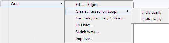
You can use these options to choose how face zones are processed within objects, prior to wrapping.
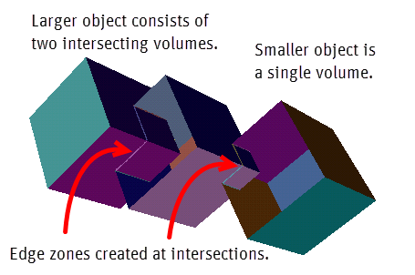
Within each object, edge zones are created on the loops where the face zones overlap. In Figure 7.58: Individual Object Loop, after applying > to all objects, only one such edge zone is created - in the large geometry object at the intersection of the two cubic volumes.

Edge zones are created on the loops where face zones overlap, both within a single object and between multiple objects. In Figure 7.59: Collective Object Loops, an additional edge zone is created where the large geometry object intersects the smaller object.
You can determine the surfaces and features which need to be captured with higher accuracy based on the usage of the model. For example, when using a car model for an external aerodynamic simulation, the recovery of external surfaces requires greater accuracy. Other components like the braking system or underhood components can be recovered with lower accuracy since they are not as significant for the simulation.
The recovery of features and surface mesh quality are controlled by setting the Geometry Recovery attribute for objects or face zones in the Geometry Recovery Options dialog box. The wrapped surface mesh inherits the geometry recovery attribute from the underlying objects or face zones.
- Low
enables you to create a rough wrapped representation of the selected objects. Features are not preserved and the mesh quality is not as good as a CFD mesh.
- High
enables better feature capture and high quality surface mesh. By default, the High attribute is set for all face zones in the mesh.
To set the geometry recovery attribute,
Right-click on any geometry or mesh object, and then select > to open the Geometry Recovery Options dialog box.
Select the objects or face zones in the selection list.
Click for the appropriate option in the Geometry Recovery group box.
To visualize the geometry recovery option, use the hot key Ctrl+Shift+C to go to Color Options Mode, then Ctrl+G to apply color by geometry recovery.
The region/volume of interest should be well connected before the volume mesh can be generated. Any holes or leaks need to be located and fixed before proceeding with volume meshing. Holes/leaks can be located using a material point. When you select the material point and set the minimum and maximum limits for the hole size, those locations, within the set size limits, at which a path traces back to the material point through the geometry are recognized as holes or leaks.
When you refine an existing region or specify additional sizing functions for better representation of the geometry, the minimum size may be reduced to a size smaller than some existing leakages. These leakages can be detected automatically using the automatic hole detection tool in Ansys Fluent Meshing. The refinement of a region may result in the joining of previously separate regions through cells newly introduced by the refinement (region collision). While refining a region, Ansys Fluent Meshing will automatically detect cells causing region collision and group them. Such groups of cells will be identified as holes in the region. The number of holes exposed by the current refinement will be reported in the console.
The following operations allow you to automatically detect holes:
Refining a single region.
Specifying local size function and additional zone-specific sizes after initialization.
Refining local regions defined according to requirements.
╧
You can use the Fix Holes dialog box to locate and fix such holes as described in the following generic procedure:
Right-click on the selected geometry or mesh object(s) in the Model tree and then select > .
You can add or change Objects using the selection list in the dialog box. Click to display only the selected object(s) in the graphics window.
Select an appropriate material point.
The default material point (external) is a suitable point, external to the selected objects. Click to enable the Material Point drop-down list, if necessary.
Retain the Use Size Field option, if required.
This will use a size field based on previously defined size controls or size functions to determine the limits for hole sizes.
Set a Resolution Factor if desired.
Setting a value less than 1 can help to find holes not aligned to the Cartesian axes by using finer sampling than the given size field.
In situations where a hole's minimum size is larger than the size field's minimum size, using a Resolution Factor helps to find holes without modifying the size field. That is, you can use the same size field for both hole fixing and wrapping.
Set the minimum and maximum limits for the Hole Sizes under consideration.
The size values enable you to limit the search for holes to a relevant subset based on the size range. As you locate the respective holes and fix them, the possibility of false holes is reduced.
You can click to check the sizes on the geometry; click Draw to turn off size display.
In situations where a hole's minimum size is larger than the size field's minimum size, using the Resolution Factor helps to find holes without modifying the size field. That is, you can use the same size field for both hole fixing and wrapping.
You can alternatively choose to use a specific size to find the holes or leaks in the mesh.
To find holes based on a specified size, disable Use Size Field. Enter an appropriate value for Min Size and click .
The Max Size can be set to limit the search to a relevant size range.
Click to locate all the holes based on the specified parameters.
The number of holes is reported in the Count field in the Wetted Holes group box.
Using the Pan Regions Dialog Box
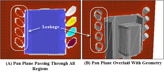
The options in the Pan Regions dialog box enable you to observe and analyze the region to be wrapped, overlayed on a plane aligned with the Cartesian grid. The plane can be passed through the selected region (or all available regions) along the X, Y, or Z direction, as required. The interior of the selected region(s) is displayed on the plane, at every position of the plane. Click to open the Pan Regions dialog box.
You can also overlay the boundary surfaces while panning, and clip the boundary surfaces on either side of the cutting plane.
To pan through all the regions of your choice, do the following:
Display the required region (using the Draw button below the Regions list).
Click the Pan Regions... button to open the Pan Regions dialog box.
Select the appropriate axis along which you want to pan through the selected regions from the Direction list.
The Start, End, and Increment fields will be updated automatically based on the cell size distribution of the Cartesian grid. You can change these values as appropriate.
Enable Overlay Graphics if you want to see the geometry along with the pan plane.
Select Positive or Negative to clip the surfaces on the positive or negative side of the cutting plane. Figure 7.60: Overlaid Geometry Clipped with the Pan Plane shows the geometry on the positive side of the cutting plane.
Select the regions to be analyzed in the Region selection list. By default, all regions are selected. In cases comprising a large number of Cartesian regions, you can pan through selected regions instead.
Click Pan to start the plane movement through the selected regions.
Alternatively, use the arrow buttons or the slider to manually move the pan plane to a particular location.
The interior of the Cartesian grid is displayed on every position of the plane during its movement through the region. Increase (or decrease) the Increment value to increase (or decrease) the speed of movement of the plane.
Figure 7.61: Leak Detection Using the Pan Regions Dialog Box shows how the leakage can be detected using the Pan Regions dialog box. If, at any position of the plane, the color of the region is seen inside the geometry, there may be a leak or hole in the Cartesian grid.
Adjust the plane at the position where the leak is seen on the plane.
Warning: The Pan Regions dialog box only enables you to know whether or not there is a leak or hole in the geometry. If the geometry has a hole or leak, you need to find its exact location and fill it.
Closing holes
Options for closing or opening the holes are in the Operations group box:
You use the Wetted Holes group box to traverse the holes detected, or to globally patch or open all the holes.
Click to view all the wetted holes detected.
Click to view the first hole. The display will be limited to the region of the hole.
Click repeatedly to traverse all the wetted holes and examine them individually.
Click to automatically patch all the wetted holes detected.
Click to open all the wetted holes detected (when the holes identified do not represent actual holes).
You use the Selected Holes or Create Patch group box to close the displayed hole individually.
Click to automatically close the currently displayed hole.
Click if the currently displayed hole does not represent an actual hole. Opening a hole enables you to indicate that the approximated wetted region should propagate through the configuration detected as a hole.
Click if the currently displayed hole is not relevant for the object wrapping/sewing operation.
Click to open the Cylinder dialog box to create a cylindrical surface to fix the hole.
You use the Trace to Points group box to locate holes or leaks by tracing a path from the Material Point to a selected Target Point through all the objects. Even after you fix the holes/leaks, you can use the options to verify that no tiny leaks remain.
Select a point from the Target Points selection list and click .
The path connecting the target point to the material point will be highlighted and will pass through the hole/leak.
Fix the hole using the options in the Wetted Holes, Selected Holes, or Create Patch group box, as appropriate.
Click in the Wetted Surface group box to update the wetted surface representation.
Click in the Trace to Points group box and then click Trace again to locate any remaining holes/leaks.
Repeat the hole fixing steps as needed to ensure no holes/leaks remain.
You use the options in the Wetted Surface group box to view the approximate representation of the volume or region of interest based on the objects and material point selected. You can also create a mesh object using the shrink-wrap method.
Click to view the approximate representation of the wetted surface, based on the objects and material point selected. Enable Overlay Graphics to view the object(s) along with the wetted surface.
Click to hide the wetted surface in the graphics window.
Click to update the wetted surface representation after any hole fixing operations (patch, open, creating caps, and so on) are performed.
Examine the updated region for further leaks or holes. Fill any remaining leaks or holes before proceeding.
After all the holes/leaks are fixed you can proceed to wrap the objects. Specify an appropriate New Object Name and New Label Name (if required). Click to create a mesh object for the selected objects using the shrink-wrap method.
Important: The octree refinement used to identify and repair holes occurs in a different order than when used to wrap objects. Thus, using this button may generate a different mesh than if you use the Wrap dialog box as described in Shrink Wrapping the Objects
The Wrap dialog box contains options for shrink wrapping the selected objects. Select the objects to be wrapped in the Outline View and then select > from the context sensitive menu to open the Wrap dialog box.
Select the appropriate option, Individually or Collectively, from the Target list. These options are described in Creating Individual Mesh Objects and Creating a Collective Mesh Object.
Creating Individual Mesh Objects
The Individually option enables you to create a conformal surface mesh for each object selected. A well-connected mesh object and corresponding zones will be created for each object. The mesh object name is the original object name with the suffix -mesh. This operation uses a suitable material point that is external to the objects selected. Hence, any internal voids or features will be eliminated. The mesh objects created are suitable for repair operations such as gap or thickness removal, or as the final surface mesh.
Figure 7.62: Wrapping Individual Objects shows the mesh objects created for geometry objects using the Individually option.
Creating a Collective Mesh Object
The Collectively option enables you to create a single, well-connected mesh object and corresponding zones, based on the objects selected. You can specify an appropriate name for the mesh object and a new label name.
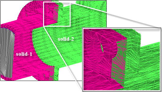
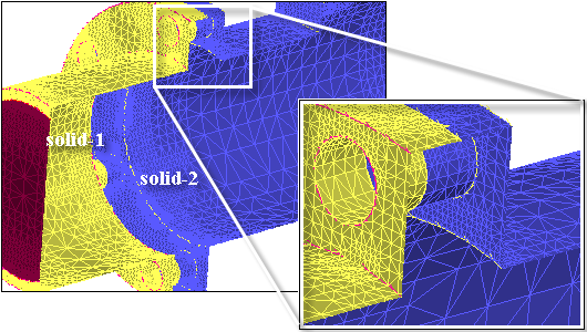
When you select external in the Material Point drop-down list, a suitable reference point external to the objects is selected for the object wrapping operation. Hence, any internal voids or features will be eliminated. Figure 7.63: Multiple Solids shows an example with multiple solid objects. The aim of the object wrapping operation is to mesh the solids conformally and create a single solid cell zone in the final mesh. Figure 7.64: Single Solid Surface shows the mesh object created, where the multiple solids are unified.
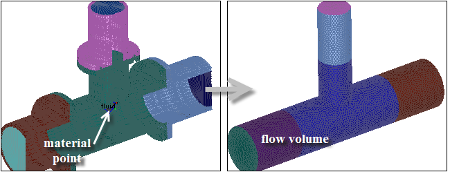
Alternatively, you can use this option to create the flow volume, when the surrounding solids are not needed in the final mesh. All objects bounding the flow volume should be selected for the wrapping operation. Select the appropriate material point needed to identify the “wetted” region that is the flow volume. The material point can be defined in the Material Points dialog box.
Figure 7.65: Extracting the Flow Volume shows the extraction of the internal flow volume for a T-junction by specifying a material point and using the Fluid Surface option.
For the Collectively option, specify the New Object Name and New Label Name.
Set the Resolution Factor. This field can be used to set sampling coarser or finer than the final surface mesh.
Tip: For industrial size problems where the geometry recovery is set to high, it is recommended that the resolution factor not be smaller than 0.7.
Important: Wrapping models with a large number of face zones may cause significant slow down in performance. Merging face zones with the same boundary conditions will improve the efficiency of the wrapping operation.
Important: When wrapping large, complex geometries with small mesh sizes, you may need to increase the memory allocation. From the > menu, select in the Categories drop down list, and specify a new value for Max Octree Memory.
Important: By default, the initial bounding box for shrink wrapping is the global bounding box. In multiple session wrapping, a newly created wrapper surface may increase the global bounding box, which affects subsequent wrapper results. To avoid this issue, go to the + menu, select in the Categories drop down list, and choose selection for the Initial Bounding Box.
You can use the command /objects/wrap/wrap to create the mesh object. Specify the objects to be wrapped and other relevant parameters.
The command /objects/wrap/set/shrink-wrap-rezone-parameters enables you to set the parameters for improving the mesh object surface quality using rezoning. The geometry object zones will be separated based on the separation angle specified to improve the feature imprinting on the mesh object.
The options in the Improve dialog box enable you to improve the surface mesh quality of mesh objects.
The wrapper surface created after imprinting is of good quality and it represents the input geometry very well in most regions. However, you can improve it further in some regions of the geometry such as sharp corners and curves. The post wrapping improvement operations allow you to improve the wrapper surface by performing various operations such as smoothing, swapping, inflating thin regions, removing crossovers, and so on.
Select the mesh objects in the Outline View. Right-click and select > from the context sensitive menu.
Choose the appropriate Method.
The Smooth and Improve option improves the mesh by a combination of smoothing, swapping, and surface mesh improvement operations. Object normals are correctly oriented and island faces are also deleted. You can optionally coarsen the surface mesh by specifying a suitable Coarsening Factor. Additional Imprint operations can be done to improve feature capture on the surface mesh.
Note: Using the Imprint option may result in quality deterioration.
The Surface Remesh option improves the mesh by remeshing based on the current size field. Object normals are correctly oriented and island faces are also deleted.
Set Coarsening Factor and Imprint as desired.
The wrapper surface created may be finer than you require in some regions. You can coarsen the mesh in such regions or globally for the entire wrapper surface. This operation also reduces the cell count of the mesh, thereby reducing the computation time.
Click Improve.
Note: Additional controls can be set in the Objects category in the > dialog box for improving the mesh object quality.
Enable the Improve Quality Aggressively option to collapse faces without preserving boundary features. This option is disabled by default.
You can alternatively use the command /objects/improve-object-quality.
The following object wrapping options are available:
Surfaces in close proximity constitute thin regions in the mesh. Examples of thin regions include sharp corners, trailing edge configurations, and so on, which may not be recovered accurately enough during the object wrapping operation and surface elements may span between nodes on the proximal surfaces.
You can use the command /objects/wrap/set/include-thin-cut-edges-and-faces to enable better recovery of such configurations during the object wrapping operation.
The command /objects/wrap/set/report-holes? enables you to check for holes in the object created. Holes, if any will be reported at the end of the object wrapping operation.
The command /objects/wrap/set/max-free-edges-for-hole-patching enables you to set the maximum number of free edges in a loop to fill the holes.
The command /objects/wrap/check-holes enables you to check for holes in the objects. The number of hole faces marked will be reported.
The command /objects/improve-feature-capture enables you to imprint the edges comprising the mesh object on to the object face zones to improve feature capture for mesh objects. You can specify the number of imprinting iterations to be performed.
Note: The geometry objects used to create the mesh object should be available when the improve-feature-capture command is invoked. Additionally, the face zones comprising the objects should be of type other than geometry.