


This chapter describes the use of objects and material points for identifying the mesh region.
An object—generally a set of face zones and edge zones—is used to identify the domain to be meshed. By including edge zones in the object definition, you are able to capture the object features even when wrapping.
Objects are generally closed solid volumes, closed fluid (wetted) volumes, capping surfaces, or individual face zones that can be used for meshing. For example, using capping surfaces in conjunction with a material point and a closed solid volume enables you to extract the flow volume using wrapping.
Objects (defined or imported) are independent of each other; that is, objects do not share face and/or edge zones. In cases where objects are defined using a common face/edge zone, the common face/edge zones are duplicated to make the objects independent.
Object Based Meshing
Objects can be used for mesh generation as described:
- Surface Meshing
Object wrapping or join and intersect operations are used to create a conformal, connected surface mesh. This is the first of a two-step process for creating a tetrahedral, hexcore, polyhedral, or hybrid mesh in meshing objects. This process is described in Object-Based Surface Meshing.
- Volume Meshing
The Volumetric Regions are calculated from the conformal, connected surface mesh, and then filled with tetrahedral, hexcore, or polyhedral mesh, with or without inflation layers. This is the second of a two-step process for meshing objects and is described in Object-Based Volume Meshing
- Auto Mesh
An object-based workflow to generate a volume mesh. You can select the desired mesh object in the Model tree and select from the menu available. Alternatively, use the > menu to open the Auto Mesh dialog box, then select the mesh object in the Object drop-down list.
See Using the Auto Mesh Dialog Box or Meshing All Regions Collectively Using Auto Mesh for details on using the Auto Mesh dialog box.
Note: The No Fill option is not available when a mesh object is selected for volume meshing.
- Auto Fill Volume
A selective workflow to generate a volume mesh on selected volumetric regions. You can select the desired Volumetric Regions in the Model tree and select Auto Fill Volume from the menu available. See Meshing Regions Selectively Using Auto Fill Volume.
- CutCell Meshing
A general purpose, hex-dominant meshing technique using a direct surface and volume approach. Objects can be used to determine the inclusion of Cartesian grid entities for CutCell meshing. The Cartesian grid will be refined and snapped to any face zone included in the objects selected for CutCell meshing. See Generating the CutCell Mesh.
Objects descriptions include attributes (type, cell zone type and priority) and entities (face zone labels, volumetric regions and cell zones).
You can manage your objects using several tools accessible with hotkeys, onscreen tool buttons, text commands, or by using tools in the Manage Objects dialog box. Tools exist for operations such as object creation, modification, changing properties, alignment, remeshing, deleting, merging, and moving.
Each object has attributes such as object type, cell zone type, and priority.
- Object Type
The following object types are available:
- Geometry
Objects imported through CAD using the CAD Faceting option (see Importing CAD Files) or created for a given geometry. The geometry objects may be non-conformal.
- Mesh
Objects that are good quality surface mesh representations of the geometry. Mesh objects may contain multiple volumes with shared faces. They may be imported using the CFD Surface Mesh option for CAD import or created using the object wrapping options. Mesh objects can also be created using the Sew operation.
- Cell Zone Type
The object cell zone type indicates the type of cell zone created when the mesh is generated based on objects.
Figure 7.10: Mesh With Different Cell Zone Types shows a CutCell mesh with different cell zone type assigned to respective objects.
- Priority
The object priority controls the inclusion of the mesh entities. In case of overlapping objects, the entities in the overlapped region will be included with the object having a higher priority value.
Figure 7.11: Use of the Object Priority for Overlapping Objects shows an example with overlapping objects. The overlapped region is included with the zone corresponding to the object having the higher priority value (in this case, 4).
Note: Multiple objects having the same priority assigned will be merged into a single cell zone, irrespective of cell zone type.
Priority is also important when objects are created for bounding boxes or wind tunnels, and so on. In such cases, the object created for a bounding box or wind tunnel must be assigned the lowest priority.
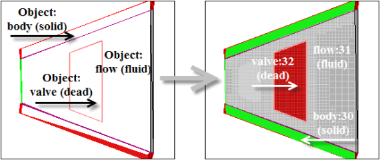
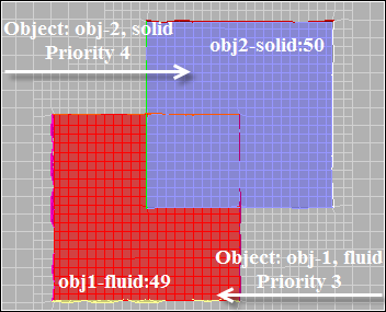
Figure 7.12: Creating Objects—Example shows the Subtract method for creating objects, using an example with three non-intersecting bodies.
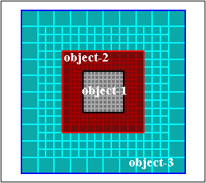
The order of priority assigned to individual objects is important when using the Subtract method. Zones in higher priority objects will be ignored when defining lower priority objects. In this case the order of priority is object-1 > object-2 > object-3.
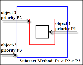
Select the face and edge zones comprising the innermost body, set the Cell Zone type, and set the highest Priority value.
Select the face and edge zones comprising the inner body, set the Cell Zone type, and set an intermediate Priority value.
Select the face and edge zones comprising the outer body, set the Cell Zone type, and set the lowest Priority value.
Note: Objects (defined or imported) are independent of each other; that is, objects do not share face and/or edge zones. In cases where objects are defined using a common face/edge zone, the common face/edge zones are duplicated to make the objects independent.
Object entities include face zone labels, volumetric regions, and cell zones. Volumetric regions and cell zones are available only for mesh objects.
Face zone labels: For geometry objects, these are groups of face zones comprising the object. For mesh objects, these are original CAD zones or bodies, or face zones comprising the mesh object. If the mesh object is created by merging multiple mesh objects, the face zone labels represent the objects that were merged. They provide the link to the original geometry.
When the CAD Assemblies option is selected for CAD import, you can set up labels for the CAD zones, if required. Named Selections are also imported as labels. These labels are preserved throughout the object-based meshing workflow in Fluent Meshing.
Several tools for managing Face Zone Labels are available via the context-sensitive menus.
Note: Geometry objects can contain unlabeled zones. Mesh objects always contain face zone labels which are derived from the associated geometry objects. In case of unlabeled zones in the geometry object, the mesh object face zone label is the same as the associated geometry object.
Volumetric regions: These are finite, contiguous domains that are ready for volume meshing.
Cell zones: These are created when the volume mesh is generated.
Various options are available for face zone labels via the context-sensitive menus in the tree:
The context-sensitive menu for Face Zone Labels contains options for drawing and selecting all labels and obtaining an overall summary or detailed information about the face zone labels.
For Geometry Objects, you have these additional options:
Unlabeled face zones can be labeled using the Create Labels... option.
The Create Labels dialog box opens. Select the face zones from the Face Zones selection list and specify an appropriate Label Name. For geometry objects, you can choose to list all available object face zones or only unlabeled object face zones for selection. Enable the Create a label for each face zone checkbox to generate an individual label for each face zone.
Use the Remove All Labels from Zones... to remove labeled face zones from an object.
The Remove All Labels dialog box opens. Select the Object and Labeled Face Zones, and then click .
Note: Unlabeled face zones are not supported for Mesh objects.
Unlabeled zones can be drawn and/or selected without having to create a new label using the Unlabeled Zones... options.
For Mesh Objects, you have the additional Join/Intersect... option which opens a dialog box to assist with creating a conformal surface mesh.
The context-sensitive menu for individual labels contains options for renaming, merging, and deleting face zone labels in addition to the standard options for drawing and selecting all labels, and obtaining an overall summary or detailed information.
You can also add or remove zones from an existing face zone label.
Select Add Zones... from the context sensitive menu to open the Add Zones to Label dialog box. Select the face zones and click . For geometry objects, you can add unlabeled zones or those already included in other labels within the object selected.
Select Remove Zones... from the context sensitive menu to open the Remove Zones from Label dialog box. Select the face zones and click .
For Mesh Objects, the context-sensitive menu for individual labels contains additional options for:
connecting the face zones using Join/Intersect....
finding and repairing face connectivity and quality problems using Diagnostics....
creating or recovering periodic boundaries using Recover Periodic....
You can manage your objects using several tools accessible with hotkeys, onscreen tool buttons, text commands, or by using tools in the Manage Objects dialog box.
Tools exist for operations such as object creation, modification, changing properties, alignment, remeshing, deleting, merging, and moving.
Tools for the most common object management operations are accessible via hotkeys, icons, or text commands.
- 7.3.1.3.1.1. Creating Objects for CAD Entities
- 7.3.1.3.1.2. Creating Objects for Unreferenced Zones
- 7.3.1.3.1.3. Creating Multiple Objects
- 7.3.1.3.1.4. Easy Object Creation and Modification
- 7.3.1.3.1.5. Changing Object Properties
- 7.3.1.3.1.6. Automatic Alignment of Objects
- 7.3.1.3.1.7. Remeshing Geometry Objects
- 7.3.1.3.1.8. Creating Edge Zones
When the CAD Assemblies option is selected for CAD import, the CAD entities can be used to create or modify geometry/mesh objects. The objects are associated with the CAD entities (which are then locked), enabling re-importing or updating of selected parts or bodies using different faceting qualities and topology representations for quick design changes and updates.
Use the options in the menu for CAD entities for creating geometry/mesh objects and modifying existing objects. Select the CAD entities in the tree and then choose the appropriate menu option. Alternatively, select the CAD objects in the graphics display and select the option from the CAD Tools. See Creating and Modifying Geometry/Mesh Objects for details.
Use the options in the menu for geometry/mesh objects for modifying the selected objects based on the associated CAD entities. You can also attach or detach the CAD entities from the objects. See CAD Association for details.
Use the options in the Create Objects dialog box to define objects for unreferenced boundary face zones and edge zones. Right click Boundary Face Zones in the Unreferenced branch of the tree and select Create New Objects... from the context-sensitive menu.
Enter an appropriate name in the Object Name field.
You can also have the object name generated automatically by leaving the Object Name field blank. In this case, the object name will be assigned based on the Prefix, cell zone type, and priority specified (for example, an object named object-fluid:3-20 has prefix object-, cell zone type fluid, priority 3, and object ID 20).
Select the appropriate option from the Cell Zone Type drop-down list.
Set the priority.
Select the appropriate type from the Object Type drop-down list (default, geom).
Enable the Create a label for each face zone checkbox to generate an individual label for each face zone.
Click .
You can also create one object per selected zone using the command /objects/create-multiple. This is particularly useful for CAD exported models, as you can define an object per part. An object will be created for each selected zone and will be named automatically based on the specified prefix and priority. The name assigned is prefix face zone name-priority:object ID. (For example, an object named object-wall-3:20 will be created for the face zone wall, with the specified prefix object- and priority 3. The object ID is 20.)
Specify the first and last zone for which objects are to be created. You can also use wild-cards for specifying the face zones to be considered.
Note: You need to specify valid zone names or IDs.
Specify the prefix to be used for the object name and the cell zone type.
Specify the priority for the first object (for the first zone selected) and the increment in priority.
When the increment is set to a value greater than zero, the priority will be assigned in the order of face zone ID. If the increment is set to zero, all objects will have the same priority.
A geometry object will be created for the first and last zone (as specified) and for all valid face zones having IDs between the first and last zone.
You can easily move a zone from one object to another or create a new object using the Transfer Zones tool (![]() ) or Ctrl+Shift+Y hotkey combination.
) or Ctrl+Shift+Y hotkey combination.
Select the zone(s) to be moved or to form a new object.
Press the hotkey combination or click
 .
.If a target object is set, the selected zone(s) are moved to the target. If no target is set, enter the new object name in the Create Geometry Object dialog box.
To set a target object,
Select the object using the mouse probe.
Press the hotkey combination Ctrl+S or
 .
.
Note: Empty objects will be automatically deleted.
Use the Change Object Properties dialog box to change the properties of objects based on selections in the graphics window. Select one or more objects and then use the hot-key Ctrl+Shift+N to open the Change Object Properties dialog box.
Alternatively, select the objects in the Model tree and then select Rename/Change Properties... from the menu available to access the Change Object Properties dialog box.
If a single object is selected, you can specify a new object name. If multiple objects are selected, you can specify a common prefix for the objects selected. This enables you to easily view the objects with the same prefix using the tree view button for selection lists. You can also choose to rename object zones and set the geometry recovery option for the object zones (high or low).
You may also fit objects together in precise alignment, for example to position a flange on a body by aligning bolt holes.
The procedure is initiated via the hotkey Ctrl+Shift+G, and uses a temporary local coordinate systems (LCS) to achieve the alignment.
Defining a local coordinate system by selecting 1-6 nodes works as follows:
If only 1 node is selected, the LCS origin is at the node location and axes are aligned to global coordinate system.
For 2 nodes, the LCS origin is at the midpoint of nodes and axes are aligned to global coordinate system.
For 3 nodes, the origin is at the first point, the LCS x-axis is along a vector from the first to the second point, and the LCS y-axis is along a vector from the first point to the 3rd point.
For 4, 5 or 6 nodes, the first 3 points define a circle. The LCS origin is at the center of the circle and the z-axis is normal to the circular plane (positive direction is determined by the right-hand rule).
For 4 nodes, the x-axis is defined by a vector from the center of the circle to the projection of the 4th point on the circular plane.
For 5 nodes, the x-axis is defined by a vector from the center of the circle to the projection of the mid-point of 4th and 5th points on the circular plane.
For 6 nodes, the x-axis is defined by a vector from the center of the circle to the projection of the circumcenter of 4th, 5th and 6th points on the circular plane.
You can create mesh objects from the geometry objects without wrapping by using the Remesh dialog box.
Select in the context-sensitive menu for geometry objects to open the Remesh dialog box.
Select Individually or Collectively from the Target list.
Enter the object name when using the collective option.
Click .
The size field based on currently defined sizing controls or size functions will be used to remesh the geometry objects.
You can create edge zones on selected face zones or selected surfaces using the onscreen tools or context menus. This feature is described in Extract Edge Zones.
The Manage Objects dialog box contains options that enable you to define objects and perform certain object manipulation operations.
Right-click on Model in the tree and select Object Management... from the menu to access the Manage Objects dialog box.
Select the Objects, Face Zones, or Edge Zones from their respective lists as required. Filtering and the support of wildcards, such as *, ?, [], Boolean NOT (^), Boolean AND (&), as well as Boolean OR (|), is available for each.
Note: If edge zones are to be included in the object definition, they must have been created and visible in the lists.
List all zones controls how face and edge zones are listed.
If enabled, all available zones are listed.
If disabled, the lists will contain only zones that are not included in existing objects. You can use this to identify zones that are not associated with objects.
Select Object Zones controls highlighting of face and edge zones in the lists. If enabled, when an object is selected, face and edge zones in the object will be highlighted.
Choose one of the tabs to access the object management tools.
You can define the objects using the options in the Definition tab of the Manage Objects dialog box.
Enter an appropriate name in the Object Name field.
You can also have the object name generated automatically by leaving the Object Name field blank. In this case, the object name will be assigned based on the Prefix, cell zone type, and priority specified (for example, an object named object-fluid:3-20 has prefix object-, cell zone type fluid, priority 3, and object ID 20).
Select the appropriate option from the Cell Zone Type drop-down list.
Set the priority.
Select the appropriate type from the Object Type drop-down list (default, geom).
Click .
You can modify the object definition using the Change option in the Manage Objects dialog box. Select the object to be modified, make the necessary changes in the Definition tab, and click .
You can also use the option in the menu available for geometry objects.
Objects can be deleted using the option in the Definition tab. You can also enable Include Faces and Edges to delete the faces and edges comprising the object, when the object is deleted.
Note: When an object is deleted along with the face and edge zones comprising the object, any corresponding face/edge groups will also be deleted.
The following object manipulation operations can be performed using the options in the Operations tab of the Manage Objects dialog box or using the options from the menu available on any geometry or mesh object selected in the Outline View:
Objects of the same type (geometry or mesh) can be merged using the option. Specify the name for the merged object in the Merge Objects dialog box.
When multiple mesh objects are merged, the face zone labels represent the objects that were merged.
Important: Merging zones that have different face zone labels will result in a merged zone with the original labels appended.
Wall face zones comprising objects can be merged using the option.
The edge zones comprising an object can be merged into a single edge zone using the Merge Edges option.
Note: If the object contains edge zones of different types (boundary and interior), the edge zones of the same type (boundary or interior) will be merged into a single edge zone.
Intersection loops can be created within an object or between objects using the options in the Intersection Loops group box.
Edge zones can be extracted from the face zones included in the specified objects, based on the feature angle value specified using the options in the Edge Zones group box. You can specify whether only feature edges or all edges are to be extracted for the objects selected. Previously created edges will automatically be disassociated from the object and added to the Unreferenced branch of the Outline View tree.
Note:This functionality is also available in the Extract Edges dialog box. See Extract Edge Zones
Similar functionality is also available in the Feature Modify dialog box and Surface Retriangularization dialog box. See Creating and Modifying Features and Remeshing Boundary Zones.
A face group and an edge group comprising the face zones and edge zones included in the specified objects can be created using the options in the Zone Group group box.
The face zones comprising the object can be separated based on the angle or seed specified using the options in the Separate Faces group box.
When the face zones and/or edge zones comprising an object are deleted, you will be prompted to update the object definition. You can use the command
/objects/updateto update the defined objects per the changes.You can rename the face and edge zones comprising the object based on the object name and also specify the separator to be used.
The following object transformation operations can be performed using the options available in the Transformations tab of the Manage Objects dialog box:
Objects can be rotated using the Rotate option. Specify the angle of rotation and the pivot point and the axis of rotation by selecting 1-6 nodes in the graphics window.
The pivot point and the axis of rotation can be defined by selecting 1-6 nodes as follows:
If only 1 node is selected, the pivot point is at the node location and the axis of rotation is the global z-axis.
For 2 nodes, the pivot point is at the midpoint of the nodes selected and the axis of rotation is the global z-axis.
For 3 nodes, the pivot point is at the first node selected. The axis of rotation is the local z-axis normal to the plane defined by the three points, the positive direction is determined by the right-hand rule.
For 4, 5 or 6 nodes, the first 3 points define a circle. The pivot point is at the center of the circle. The axis of rotation is the local z-axis normal to the circular plane, the positive direction is determined by the right-hand rule.
Objects can be scaled using the Scale option. Specify the scale factors (X, Y, Z) for the scaling operation.
Objects can be translated using the Translate option. Specify the vector components to define the translation, or click Define and select two screen locations to determine the translation.
In addition to objects, material points can be defined to allow the mesher to separate the cell zone. Typically, a material point can be defined to retrieve a cell zone for which an object cannot be defined, or the object definition alone is not sufficient to retrieve the cell zone. Material points can also be used to retrieve regions from a non-contiguous cell zone. Contiguous regions will be separated based on the respective material points defined. The cell zone retrieved based on the defined material point will be of the type fluid and have the specified name.
The following examples demonstrate the use of a material point in addition to objects:
Some cases involving “dirty” geometry may result in multiple voids. In this case, the volume to be meshed can be recovered by defining an object comprising the zones enclosing the domain to be meshed, combined with a material point within the expected meshed domain (see Figure 7.14: Using Material Points—Example).
Note: The intersection loops can be created (see Object Manipulation Operations) to recover the intersecting features accurately.
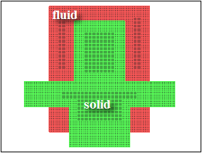
In Figure 7.15: Example—CutCell Mesh, Only Objects Defined, the use of only objects to define the meshed domain results in a mesh with two cell zones, solid and fluid.
By specifying a material point in addition to the object definition (fluid or dead), the fluid zone in Figure 7.15: Example—CutCell Mesh, Only Objects Defined will be further separated into a fluid zone (containing the material point) and a dead zone (see Figure (A)). If
auto-delete-dead-zones?is enabled (default), the separated dead zones will be deleted automatically (Figure (B)).(A) CutCell Mesh—Material Point and Objects Defined,
auto-delete-dead-zones?Disabled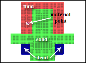
(B) CutCell Mesh—Material Point and Objects Defined,
auto-delete-dead-zones?Enabled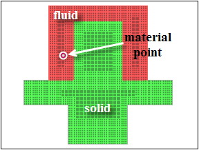
Note: For cases where a single region is separated by a double-sided surface (fan, radiator, or porous-jump), you need to define a material point for each of the regions to be recovered (that is, both upstream and downstream of the double-sided surface). Separate cell zones will be recovered for each region on either side of the double-sided surface.
You can merge the cell zones manually after the mesh has been generated.
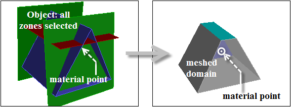
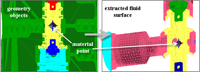
Figure 7.16: Example—Fluid Surface Extracted From Geometry Objects and Material Point shows the use of a material point in addition to objects defined to extract the internal fluid surface, using the object wrapping operation.
Right-click Model in the tree and select Material Points... from the menu to access the Material Points dialog box.
Click Create... to open the Create Material Point dialog box. Follow the process described.
Select the appropriate zones or objects in the graphics window. The selections should be such that the material point created will lie at a central point in the fluid domain.
Click to obtain the material point coordinates based on the selections.
You can also specify the coordinates manually if the material point location is known.
Enable Preview to verify that the location is appropriate.
Enter an appropriate fluid zone name in the Name field.
Click .
Use the List button to display the x-, y-, and z- coordinates of the selected material point(s) in the console.
Use the Delete button to remove the selected material point(s).
Use the Draw button to display the selected material point(s) in the graphics window.