


A volume mesh created from a high-quality surface mesh may contain some high-skewness cells. The poor cells may result from unsuitable mesh size distribution over the domain or, more often, are caused by constraints imposed by the boundaries.
After creating a tetrahedral or hybrid mesh, you can improve the quality of the mesh by smoothing nodes and swapping faces. Smoothing and face swapping are tools that help to improve the quality of the final numerical mesh. You can also use the improve command which combines operations like collapsing cells, node smoothing, face swapping, and inserting nodes. This chapter describes the options available for improving the mesh quality by removing highly skewed cells.
- 6.1.1. Smoothing Nodes
- 6.1.2. Swapping
- 6.1.3. Improving the Mesh
- 6.1.4. Removing Slivers from a Tetrahedral Mesh
- 6.1.5. Modifying Cells
- 6.1.6. Moving Nodes
- 6.1.7. Cavity Remeshing
- 6.1.8. Manipulating Cell Zones
- 6.1.9. Separating Cell Zones
- 6.1.10. Manipulating Cell Zone Conditions
- 6.1.11. Using Domains to Group and Mesh Boundary Faces
- 6.1.12. Checking the Mesh
- 6.1.13. Selectively Checking the Volume Mesh
- 6.1.14. Checking the Mesh Quality
- 6.1.15. Clearing the Mesh
Smoothing repositions the nodes to improve the mesh quality. The smoothing methods available are:
Laplace smoothing is used to improve (reduce) the average skewness of the mesh. In this method, a Laplacian smoothing operator is applied to the unstructured grid to reposition nodes. The new node position is the average of the positions of its node neighbors.
The relaxation factor (a number between 0.0 and 1.0) multiplies the computed node position increment. A value of zero results in no movement of the node and a value of unity results in movement equivalent to the entire computed increment.
This node repositioning strategy improves the skewness of the mesh, but usually relaxes the clustering of node points. In extreme circumstances, the unchecked operator may create grid lines that cross over the boundary, creating negative cell volumes. To prevent such crossovers, the skewness of the resulting cells is checked before the node is repositioned. This makes the smoothing operation time-consuming.
The smoothing operator can also be applied repeatedly, but as the number of smoothing iterations increases, the node points have a tendency to pull away from boundaries and the mesh tends to lose any clustering characteristics.
Variational smoothing is available only for tetrahedral meshes. It can be considered as a variant of Laplace smoothing. The new node position is computed as a weighted average of the circumcenters of the cells containing the node. The variational smoothing method is provided as a complement to Laplace smoothing.
Skewness-based smoothing is available only for tetrahedral meshes. When you use skewness-based smoothing, a smoothing operator is applied to the mesh, repositioning interior nodes to lower the maximum skewness of the mesh. Interior nodes will be moved to improve the skewness of cells with skewness greater than the specified minimum skewness. You can also specify an appropriate value for the minimum improvement, if required. This allows you to stop performing the smoothing iterations when the maximum change in cell skewness is less than or equal to the value specified for minimum improvement.
The maximum change in cell skewness will be compared with the specified value for minimum improvement. When the maximum change in cell skewness is less than or equal to the value specified for minimum improvement, further smoothing iterations will no longer yield appreciable improvement in the mesh. The smoothing will be stopped at this point even if the requested number of iterations has not been completed.
This skewness-based smoothing process can be very time-consuming, so it is advisable to perform smoothing only on cells with high skewness. Improved results can be obtained by smoothing the nodes several times. There are internal checks that will prevent a node from being moved if moving it causes the maximum skewness to increase, but it is common for the skewness of some cells to increase when a cell with a higher skewness is being improved. Hence, you may see the average skewness increase while the maximum skewness is decreasing.
You should consider whether the improvements to the mesh due to a decrease in the maximum skewness are worth the potential increase in the average skewness. Performing smoothing only on cells with very high skewness (for example, 0.8 or 0.9) may decrease the adverse effects on the average skewness.
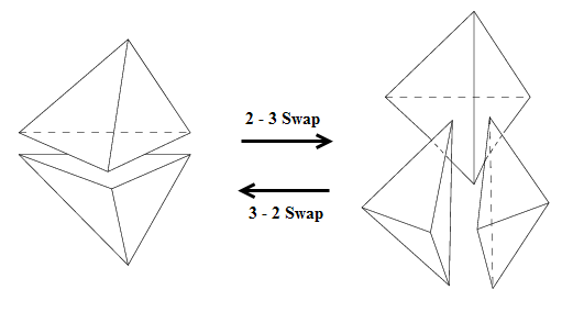
For tetrahedral meshes, swapping involves searching for a specific configuration of cells and replacing it by an alternative configuration. The default option is a 3–2 swap configuration where three tetrahedra are replaced by two tetrahedra after swapping. The other possible combinations are the 2–3 swap configuration (replacing two tetrahedra by three) and the 4–4 swap configuration (replacing four existing tetrahedra with four alternate tetrahedra).
Figure 6.1: 2–3 and 3–2 Swap Configurations shows the 2–3 and 3–2 swap configurations. The two tetrahedra (on the left) having a common interior face can be replaced by three tetrahedra having a common interior edge. The common face will be replaced by three interior faces and an interior edge during swapping. Conversely, the three tetrahedra (on the right) have two interior faces each and share a common interior edge. During swapping for a 3–2 configuration, three interior faces and the common interior edge will be replaced by a single face. This results in two tetrahedra having a common interior face.
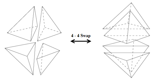
Another possible swap configuration is the 4–4 swap configuration where four tetrahedra will be replaced by four alternate tetrahedra. In Figure 6.2: 4–4 Swap Configuration, either the common interior edge or two common faces can be replaced, resulting in four alternate tetrahedra.
The Improve operation is an automated procedure for sliver removal or for reducing the maximum skewness in the mesh. The improvement is carried out by removing cells above the specified skewness threshold by collapsing cells, swapping faces, smoothing nodes, and inserting new nodes iteratively. Each operation is specialized, and the mesh will be modified only if the mesh is noticeably improved. The skewness before and after an operation is taken into account to determine the improvement. Hence, the lower the skewness of the cells involved, the larger the improvement will have to be in order for the mesh to be modified. The improve operation is a more elaborate version of the Remove Slivers option invoked from the Refinement tab in the Tet dialog box.
A sliver typically denotes a flat tetrahedral cell. Figure 6.3: Sliver Formation shows an acceptable tetrahedron.
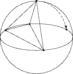
If the top node of the tetrahedron were to travel along the path of the dotted line in the direction of the arrow, as it approached the end of the line the resulting cell would be a degenerate tetrahedron, or a sliver.
In the following sections, the term sliver is used to denote all types of poorly shaped cells. There are several commands for removing slivers or to reduce the maximum skewness of the mesh.
Sliver removal operations can be invoked during the tetrahedral mesh refinement process. The Remove Slivers option in the Refinement tab of the Tet dialog box controls the removal of slivers during the meshing process. The Remove Slivers option includes operations such as collapsing cells (to remove nodes), face swapping, smoothing, and point insertion, which are invoked iteratively.
Usually the sliver cells will be removed during refinement, but occasionally a few might be left behind. In such cases, you can use the options in the Slivers tab in the Tet Improve dialog box to remove the slivers manually. The Improve command uses an automated procedure to remove slivers or to improve the mesh quality in general.
The Tet Improve dialog box contains options for removing slivers manually. The operations available for sliver removal are as follows:
Smoothing Boundary Slivers
This operation involves smoothing nodes on sliver cells having at least one node on
the boundary. During smoothing, the nodes will be repositioned so long as the skewness of
the surrounding cells is improved. The nodes on features will also be smoothed, but will
not be projected on to the original geometry. However, nodes at branch points (more than
two feature edges at the node) and end points (one feature edge at the node) will be
fixed. The nodes will be smoothed until the skewness value is less than the specified
value. The default values for the skewness threshold, minimum dihedral angle between
boundary faces, and feature angle are 0.985,
10, and 30, respectively.
Smoothing Interior Slivers
This operation involves smoothing non-boundary nodes on sliver cells having skewness
greater than the specified threshold value. The default value for the skewness threshold
is 0.985.
Swapping Boundary Slivers
A flat boundary cell containing two boundary faces can be removed by moving the boundary to exclude the cell from the zone in which it is located, effecting a minor change in the geometry. However, if there is another live zone on the other side of the boundary, this operation will result in the cell being moved to the other zone. In such cases (for example, conjugate heat transfer problems), you can decide which live zone is least critical, and then move the boundary sliver to that zone.
The default values for the skewness threshold and the minimum dihedral angle between
faces are 0.95 and 10,
respectively.
Refining Boundary Slivers
This operation attempts to increase the volume of boundary slivers to create a valid tetrahedral cell. Tetrahedra having one or two faces on the boundary are identified and then the edge opposite the boundary faces are split. The edge opposite the face pair with the largest dihedral angle will be split for a tetrahedron with one boundary face, while the edge opposite the boundary faces will be split for a tetrahedron having two boundary faces. The split node is then smoothed such that the volume of the tetrahedron increases, thereby creating a valid tetrahedral cell.
Refining Interior Slivers
This operation attempts to remove the sliver by placing a node at or near the centroid of the sliver cell. Swapping and smoothing are then performed to improve the skewness.
Collapsing Slivers
This operation attempts to collapse the edge of a skewed sliver cell on any one of its
neighbors. The default skewness threshold is 0.985.
Note:
If you are not using a two-sided wall condition for the boundary, you can slit the face zone containing the sliver (using the
/boundary/slit-boundary-facecommand) and then perform the sliver-removal operation.Multiple slivers may exist on top of each other thus, requiring multiple operations to remove them all.
Additional tools are available for you to perform primitive operations on the cells such as smoothing nodes, swapping cells, splitting cells, and so on. This section describes the generic procedure for modifying the cells using the Modify Cells dialog box. You will also use the Display Grid dialog box during the modification of the cells.
Display the cells or cell zones to be modified using the options in the Display Grid dialog box.
Select the type of entity (cell, face, node, and so on) you want in the list in the Modify Cells dialog box.
Select the entity to be modified in the graphics window.
Click the appropriate button in the group box.
The display will be automatically updated to reflect the change made by the operation.
Repeat the procedure to perform different operations on the cells.
Warning: Save the mesh periodically as not all operations are reversible.
The options in the Draw Cells group box enable drawing of cells using nodes or faces selected in the graphics window.
Use the Using Nodes option to display cells which contain the selected nodes.
Use the Using Faces option to display cells which contain the selected faces.
The operations available in the Modify Cells dialog box for modifying cells are as follows:
Smoothing Nodes
The selected nodes will be repositioned based on the average of the surrounding nodes during node smoothing. Select the nodes to be smoothed and click Smooth in the Operation group box to smooth nodes.
Splitting Cells
The selected cell will be refined by the addition of a node at the centroid of the cell during splitting. Each cell will be split into four cells.
Moving Nodes
You can move the selected node either to a specified position or by a specified magnitude.
Do the following to move a node to a particular position:
Select node in the Filter list and select the node to be moved.
Select position in the Filter list and select the appropriate position.
Click Move To in the Operation group box.
Do the following to move a node by a specified magnitude:
Select node in the Filter list and select the node to be moved.
Enter the magnitude by which you want to move the node in the Enter Selection field and press Enter.
The increment will now be selected in the Selections list.
Click Move By in the Operation group box.
Swapping Cells
You can perform either a 3-2 configuration swap or a 2-3 configuration swap. Refer to Swapping for details on the swap configurations. Do the following to swap cells:
Select the appropriate option in the Filter list and select the entities to be swapped.
Select 3 cells or the common edge in order to perform a 3-2 swap.
Select 2 cells or the common face in order to perform a 2-3 swap.
Click Swap in the group box.
Determining the Coordinates of the Centroid
Do the following to determine the centroid:
Select the appropriate option in the Filter list (cell, face, edge, or node) and select the required entity.
Click in the Operation group box.
The centroid coordinates will be printed in the console.
Determining the Distance Between Entities
Do the following to determine the distance between entities:
Select the appropriate option in the Filter list and select the two entities between which the distance is to be determined.
Click Distance in the Operation group box.
The distance between the selected entities will be printed in the console.
Projecting Nodes
You can project nodes onto a specified projection line or plane. Do the following to project nodes:
Define the projection line or projection plane, as appropriate.
Select the appropriate option in the Filter list.
Select two entities to define the projection line or three entities to define the projection plane.
Click Set in the group box to define the projection line or plane.
The line coordinates or plane position will be reported in the console.
Select the nodes to be projected.
The projection line/plane will be highlighted in the display window.
Click Project in the Operation group box.
Highly skewed meshes can be improved by moving the nodes of the cells. Moving nodes manually is a time consuming process. The node movement process for improving the mesh quality is automated. You can specify quality improvement based on the quality measure specified or based on the warp (quadrilateral elements). You can also choose between the automatic correction procedure and the semiautomatic correction procedure for the quality-based correction. You can also repair negative volume cells by moving nodes using the automatic correction procedure.
The automatic correction allows you to improve all the cells in the selected cell zone based on the specified criteria. You can also improve the cells based on the warp values.
You can access the Auto Node Move dialog box using the > menu; or by right clicking on or any individual cell zone in the tree. Selecting from the tree will automatically select the individual cell zone or all zones.
Quality-Based Improvement
For the quality-based correction, you can specify the quality limit based on the quality measure selected, dihedral angle, and the number of iterations per node to be moved. The cells which have a quality above the specified threshold limit will be selected.
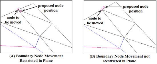
For boundary nodes, you can restrict the node movement in the plane containing each of the boundary faces sharing the node being moved. Nodes on sharp features and free edges will not be considered for movement.
The node to be moved for a particular cell will be selected based on the selection of zones in the Boundary Zones selection list and an alternative position for the node will be determined. The node will be moved to the new position only if the quality of the cell and its neighbors is improved by the change in node position. The procedure is repeated for the specified iterations per node. You can also set the number of repetitions through the automatic correction procedure as required. By default, the correction procedure is performed only once.
Warp-Based Improvement
For the warp-based correction, you can specify the maximum warp and the number of iterations per face to be improved. The quadrilateral faces which have a warp value greater than the specified maximum warp will be selected. The ideal position for the node to be moved will be determined based on the remaining three nodes. The node will be moved to the new position only if the warp of the face decreases and the cell quality does not deteriorate by the change in node position. The procedure is repeated for the specified iterations per face. You can also set the number of repetitions through the automatic correction procedure as required. By default, the correction procedure is performed four times.
The semi-automatic correction is available only for quality-based improvement. The generic procedure for using the semiautomatic correction is as follows:
Select the appropriate zones in the Cell Zones drop-down list and the Boundary Zones selection list.
Select the quality measure and specify values for Quality Limit, Iterations/Node, and Dihedral Angle as appropriate.
Enable Restrict Boundary Nodes Along Surface if required. When this option is enabled, the movement of the boundary node will be limited to the plane containing the boundary faces sharing the boundary node (see Figure 6.4: Movement of Boundary Nodes).
Click Skew to display the cell with the worst quality depending on the quality limit specified. The cell having the worst quality and cells/faces within a pre-defined range of the cell will be displayed.
Click Propose. The node to be moved and the alternative position will be highlighted. The improvement in the skewness will also be reported in the console.
If the proposed position is appropriate, click Accept; otherwise, click Refuse and then Propose to obtain the next suggestion.
Click Next Skew to proceed with the node correction for the next cell.
You can also repair negative volume cells by moving nodes. Specify the appropriate boundary zones, dihedral angle, the number of iterations per node to be moved and the number of iterations of the automatic node movement procedure (default, 1). You can also choose to restrict the movement of boundary nodes along the surface.
Cavity remeshing is useful in parametric studies because it enables you add, remove, and replace different parts of the existing mesh. You can compare alternative designs by creating a cavity around the object to be replaced and then, inserting the new object and connecting it to the existing mesh. Prisms can be grown using appropriate parameters and the cavity can be filled with cells. You can also improve the quality of the volume mesh by creating an appropriate cavity around the skewed cells and remeshing it.
You can create a cavity in an existing mesh by removing cells in a defined bounded region. The cells intersecting the bounded region will be marked and the cavity boundaries will be extracted from the marked cells. The marked cells will then be deleted to create the cavity.
The various options available are:
Removing zones: This option allows you to specify zones to be removed from the existing volume mesh.
Adding zones: This option allows you to add new zones to the existing volume mesh.
Replacing zones: This option allows you to remove a set of zones and replace them with a new set of zones.
Improving a region: This option allows you to define a cavity around skewed cells in the existing mesh. You can modify the mesh as appropriate and then remesh the cavity.
The following sections describe the cavity remeshing options:
The generic procedure for remeshing a cavity with tetrahedra using the Cavity Remesh dialog box is as follows:
Select the appropriate zones from the Remove Boundary Zones and Add Boundary Zones selection lists.
Removing Zones: Select the zones to be removed in the Remove Boundary Zones selection list. Make sure that no zones have been selected in the Add Boundary Zones list.
Adding Zones: Select the zones to be added in the Add Boundary Zones selection list. Make sure that no zones have been selected in the Remove Boundary Zones list.
Replacing Zones: Select the zones to be removed in the Remove Boundary Zones selection list and the zones to be added in the Add Boundary Zones selection list.
Improving a Region: Make sure that no zones have been selected in the Remove Boundary Zones and Add Boundary Zones selection lists.
Enable Create Face Group if you want to create a user-defined group (UDG) comprising the zones defining the cavity domain.
The cavity UDG and the corresponding cavity domain will be created, but the global domain will be retained as active when the Create Face Group option is enabled. When this option is disabled, the cavity domain will be activated when the cavity is created.
Important: The Create Face Group option is useful when using the cavity remeshing feature for large cases. For such cases, you can avoid frequent switching between domains by enabling the Create Face Group option when creating the cavity. The basic procedure is as follows:
Create a UDG for the cavity and save the boundary mesh for the cavity group defined using the File/Write/Boundaries... option (see Writing Boundary Mesh Files).
Read this boundary mesh in a separate session and create the volume mesh in the cavity as appropriate.
Save the volume mesh and read it back into the previous session using the Append File(s) option.
Connect the meshed cavity to the parent mesh and merge the cavity domain with the parent domain.
Enter an appropriate value for Scale and click Compute. The extents of the bounding box will be computed (based on the zones selected in the Remove Boundary Zones and Add Boundary Zones selection lists, and the scale factor specified) and reported in the Cavity Remesh dialog box. Alternatively, you can specify the extents of the bounding box as required.
Warning: You need to manually specify the extents of the bounding box when using the cavity remeshing feature to improve a region of skewed cells.
Specify the orientation of the bounding box in the Orient group box.
Click Draw to preview the cavity domain to be created.
Click to create the cavity domain. The boundary zones touching the cavity bounding box will be separated and included in the cavity domain along with the new zones to be added. Any zones to be removed will not be included in the cavity domain. The existing volume mesh in the cavity will be removed and boundary zones extracted from the interior zones (if any) will be changed to internal type and included in the cavity domain.
Connect the new zones with the boundaries of the cavity domain using node merging or intersect operations when removing, adding, or replacing zones in the volume mesh. Refer to Manipulating Boundary Nodes and Intersecting Boundary Zones for details. Modify the boundary mesh (if required) when improving a region in the volume mesh. Refer to Manipulating the Boundary Mesh for details on the various mesh improvement options.
Activate the cavity domain and create the volume mesh as appropriate.
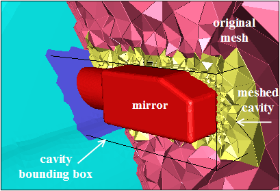
Figure 6.5: Cavity Around a Mirror Remeshed With Tetrahedra shows a cavity created around the rear-view mirror of a car. You can see the original mesh and the cavity created around the mirror and remeshed with tetrahedra. The bounding box defined for the cavity is also shown.
Activate the global domain and delete the boundary zones which are no longer required. Merge the cavity domain with the parent domain using the command
/mesh/cavity/merge-cavity.During the merging operation, the cavity cell zones will be merged with the cell zones in the parent domain. The boundaries extracted from the interior zones will be converted to interior type and merged with the corresponding zones in the parent domain. Other boundary zones included in the cavity domain will be merged with the parent face zones.
The generic procedure for remeshing a cavity with a hexcore mesh using the Cavity Remesh dialog box is as follows:
Select the appropriate zones from the Remove Boundary Zones and Add Boundary Zones selection lists.
Removing Zones: Select the zones to be removed in the Remove Boundary Zones selection list. Make sure that no zones have been selected in the Add Boundary Zones list.
Adding Zones: Select the zones to be added in the Add Boundary Zones selection list. Make sure that no zones have been selected in the Remove Boundary Zones list.
Replacing Zones: Select the zones to be removed in the Remove Boundary Zones selection list and the zones to be added in the Add Boundary Zones selection list.
Improving a Region: Make sure that no zones have been selected in the Remove Boundary Zones and Add Boundary Zones selection lists.
Note:Hexcore cavity remeshing is not supported for baffles/dangling walls.
Hexcore cavity remeshing is not supported if the mesh contains any dead cell zones.
Enable Hexcore Cavity to remesh the cavity with hexcore mesh.
Note: If this option is disabled, only the tetrahedral cells in the cavity will be replaced during the cavity remeshing.
Note: The Hexcore Cavity option is no longer supported and will be removed in a future release.
Enter an appropriate value for Scale and click Compute. The extents of the bounding box will be computed (based on the zones selected in the Remove Boundary Zones and Add Boundary Zones selection lists, and the scale factor specified) and reported in the Cavity Remesh dialog box. Alternatively, you can specify the extents of the bounding box as required.
Warning: You need to manually specify the extents of the bounding box when using the cavity remeshing feature to improve a region of skewed cells.
Note: The Orient group box will be disabled when the Hexcore Cavity option is enabled.
Click Draw to preview the cavity domain to be created.
Note: Any dead cells which intersect the cavity bounding box should be converted to fluid or solid type.
Click to create the cavity domain. The boundary zones touching the cavity bounding box will be separated and included in the cavity domain along with the new zones to be added. Any zones to be removed will be deleted from the global domain. The existing volume mesh in the cavity will be removed and boundary zones extracted from the interior zones (if any) will be changed to internal type and included in the cavity domain.
Connect the new zones with the boundaries of the cavity domain using node merging or intersect operations when removing, adding, or replacing zones in the volume mesh. Ensure that the new boundaries are properly connected with the existing boundaries. Refer to Manipulating Boundary Nodes and Intersecting Boundary Zones for details. Modify the boundary mesh (if required) when improving a region in the volume mesh. Refer to Manipulating the Boundary Mesh for details on the various mesh improvement options.
If required, create the prism layers as appropriate.
Important: To facilitate easier scripting of design changes in Hexcore meshes with prism layers using the Cavity Remeshing utility, the prism base boundary zones separated during the cavity creation are suffixed by _cavity-prism:#. This allows you to easily identify the zones to be assigned prism growth settings while remeshing.
Click Remesh to create the volume mesh in the cavity.
During the remeshing operation, the cavity cell zones will be merged with the cell zones in the parent domain. The boundaries extracted from the interior zones will be converted to interior type and merged with the corresponding zones in the parent domain. If the remeshing involves hexcore mesh generated to selected boundaries, the old boundaries will be removed and replaced during the remeshing operation.
Note: Do not change domains between the Create and Remesh operations.
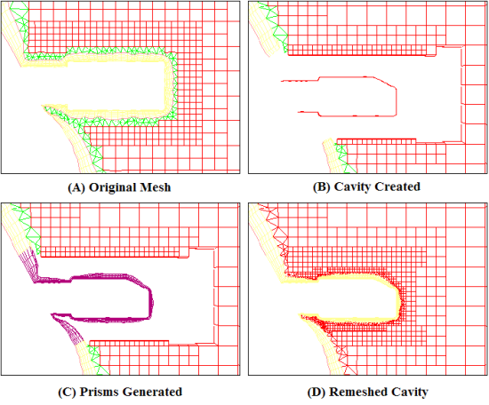
Figure 6.6: Cavity Around a Mirror Remeshed With Hexcore Mesh shows the procedure for creating a cavity to replace the rear-view mirror of a car. You can see the original mesh and the cavity created around the mirror. Prisms are then generated and the cavity is remeshed with hexcore mesh.
When a volume mesh is created (of any cell shape) from a boundary mesh, these cells will be grouped into cell zones (contiguous zones separated by boundaries). You can manipulate these zones to control further mesh generation or to duplicate an existing volume mesh to model a repeated geometry.
After the initial mesh is generated, all the cells are grouped into contiguous zones separated by boundaries. An artifact of the meshing algorithm is that a virtual zone is created outside the outer boundary, and it is always given a cell type of dead. This zone is automatically deleted upon completion of the initial mesh generation. If the initial mesh generation is interrupted for some reason, this zone will remain in the mesh until the initialization is completed. Other zone types available are fluid and solid.
The zone just inside the outer boundary is automatically set to be active and labeled a fluid zone, although you can change this type later. When refining the mesh, only the active zones are refined. By toggling the zones between active and inactive, you can refine different groups of zones independently, using different mesh parameters for the different groups.
If you plan to refine all cell zones using the same refinement parameters, change the Non-Fluid Type in the Tet dialog box before initializing the mesh. If you change the Non-Fluid Type to any type other than dead, all zones will be set active automatically after the initialization occurs. This eliminates the need for you to set all zones to be active in the Cell Zones dialog box.
If you are creating a mesh for a geometry that repeats periodically, you can simplify the meshing tasks. To do this, create the boundary and volume mesh for just one of the repeated sections. Copy the appropriate cell zones to the required locations. If the copy shares a boundary with the original zone (that is, if the two zones are connected), ensure that the distribution of nodes is the same on the two overlaid boundaries.
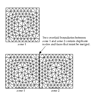
A simplified case is illustrated in Figure 6.7: Copying and Translating a Cell Zone. Here, the volume mesh was created for zone 1, and then copied and translated to create zone 2. The node distribution on the left boundary of zones 1 and 2 is the same as the distribution on the right boundary. Because the left boundary of zone 2 is overlaid on the right boundary of zone 1, there will be duplicate nodes. It is important that you merge these duplicate nodes.
The procedure for doing this is as follows:
Open the Merge Boundary Nodes dialog box.
Compare all nodes on both boundaries. To do this, select the two zones in both the Compare... and With... group boxes.
Disable Only Free Nodes for both the zones.
Click the button to merge the duplicate nodes.
After the duplicate nodes on the two boundaries have been merged, one of the two boundary face zones will be deleted automatically. Because duplicate faces are merged when the duplicate nodes are merged, one zone will no longer have any faces.
Use the Manage Cell Zone dialog box to separate out cell zones based on a specific type. For instance, you can separate out designated cell zones based on wedge-prism, hex-prism, or poly-prism type.
The procedure for doing this is as follows:
Open the Manage Cell Zone dialog box.
Select the Separate option.
Select a Type. You can choose from Wedge-Prism, Hex-Prism, or Poly-Prism.
Select one or more Cell Zones or Cell Zone Groups.
Click the button to perform the separation.
Select Draw to visualize the cell zone(s), or select List to print out valid cell zones.
You can also separate the prism cells (wedge prisms, hex-prisms, and poly-prisms) from
the cell zone using the separate-wedge-prisms,
separate-prism-from-hex or the
separate-prism-from-poly text commands from the
mesh/separate/ text command menu.
Case files read in the meshing mode also contain the boundary and cell zone conditions along with the mesh information. The Cell Zone Conditions dialog box enables you to copy or clear cell zone conditions when a case file is read.
You can copy the cell zone conditions from the zone selected in the With list to those selected in the Without list using the Copy option.
You can clear the cell zone conditions assigned to the zones selected in the With list using the Clear option.
Domains allow you to group different boundary zones together so that you can create tetrahedral meshes in the region they enclose, or you can limit the zones available for a display or report to only those zones in a selected subset of the domain, rather than the entire domain.
If you are generating a hybrid mesh containing hexahedra, tetrahedra, and pyramids, you can identify a domain of the global mesh as the region in which you want to generate tetrahedral cells. You can also use domains to group boundary zones so that you can perform diagnostics on them or display them. When you display the grid, the zones available for display will be only those zones that are included in the active domain. Similarly, diagnostic reports will report information about only those zones.
If you want to check a subset of the global domain, you can create and activate a domain that includes the desired zones, and then proceed with the display or report.
If you want your grid display or report to include all zones in the mesh, activate the global domain in the Domains dialog box.
The procedure for defining a new domain is as follows:
Deselect all zones in the Boundary Zones list and click . It is quicker to create an empty domain and then add the zones you want, instead of creating a domain with many zones and then removing those you do not want.
In the Boundary Zones list, select the zones you want to include in the new domain. If you are not sure about the zones, click Draw to display the zones that are currently selected in the Boundary Zones list.
It is possible to select all triangular or quadrilateral boundary face zones by choosing tri or quad in the Boundary Zone Groups list.
If you are creating a domain within a hybrid mesh to create tetrahedra, make sure that the domain contains all zones required to enclose the region that is to be meshed with tetrahedra, and only those zones.
If the zones you select do not completely enclose the region, or if you include additional zones that do not bound this region, the tetrahedral meshing is likely to fail or be incorrect.
Click Change. The dialog box will be updated so that the node, face, and cell zones highlighted in their respective lists are those that are affiliated with the boundary zones in the domain.
Select the domain that you want to mesh (or display or report on) in the Domains list, and then click the Activate button. This domain is then considered to be the active domain, and the Activate button is disabled until you select another domain.
By default, the most recently created domain is automatically set to be the active domain, so you only need to explicitly set the active domain if it is not the one you just created.
Note: If you are dissatisfied with the domain definition, delete it using the Delete button and start over, or modify it by selecting it and using the Change button.
When you complete the mesh generation process, you need to check the mesh before saving it.
The mesh checking capability will check the mesh connectivity and the orientation of the faces (face handedness, which should be right-handed for all faces because the solvers use a right-handed system). The domain extents and statistics for volume and face area will be reported along with the results of other checks on the mesh.
> .
The mesh check information will be printed in the console. The sample output is as follows:
 Domain extents.
  x-coordinate: min = -2.500000e+00, max = 2.500000e+00.
  y-coordinate: min = -4.357625e-15, max = 2.000000e+00.
  z-coordinate: min = -1.111022e-04, max = 2.000000e+00.
 Volume statistics.
  minimum volume: 2.297312e-09.
  maximum volume: 7.856795e-03.
  total volume: 1.953600e+01.
 Face area statistics.
 minimum face area: 1.258676e-06.
 maximum face area: 4.944555e-02.
 average face area: 1.939640e-04.
Checking number of nodes per edge.
Checking number of nodes per face.
Checking number of nodes per cell.
Checking number of faces/neighbors per cell.
Checking cell faces/neighbors.
Checking isolated cells.
Checking face handedness.
Checking periodic face pairs.
Checking face children.
Checking face zone boundary conditions.
Checking for invalid node coordinates.
Checking poly cells.
Checking zones.
Checking neighborhood.
Checking modified centroid.
Checking non-positive or too small area.
Checking face zones thread type.
 Done.
The domain extents list the x, y, and z coordinates in meters.
The volume statistics include the maximum, minimum, and total cell volume in m3. A negative value for the minimum volume indicates that one or more cells have improper connectivity. The negative volume cells should be eliminated before the computing the flow solution.
The face area statistics include the maximum, minimum, and average face area in m2. A value of zero for minimum face area indicates that one or more cells have degenerate faces. The mesh check may also fail if cells have faces with very small non-zero face areas. Such cells should also be corrected before computing the flow solution.
The topological information verified includes the number of nodes and faces per cell. A tetrahedral cell should have 4 faces and 4 nodes while a hexahedral cell should have 6 faces and 8 nodes.
Next, the face-handedness and face node order for each zone will be checked. The zones should contain all right-handed faces and all faces should have the correct node order. The modifed centroid will be checked as well which are cells that contain left-handed faces without any node order issues. Additional diagnostics can be performed for any modified centroids using the Diagnostics Tools dialog box. Besides this, the mesh check report will also display warnings based on the results of the checks previously described. If any problems are reported, you need to repair the mesh.
Note: When checking the mesh, Fluent Meshing checks all mesh data, including edges, faces, cells, and nodes that belong to geometry and mesh objects as well as unreferenced zones.
To have more control over the mesh check, use the Selective Mesh Check dialog (Selectively Checking the Volume Mesh).
If you want to check the mesh only for those parts of the mesh connected to cell zones (for the Fluent solver), use the following text commands:
/mesh/prepare-for-solve yes
/mesh/check
Note: The prepare-for-solve command removes the geometry
objects. For more information about the command, see mesh/.
Note: The mesh check will issue a warning if multiple cell zones are maintained across an
interior boundary. The boundary type in such cases should be set
to internal instead.
The mesh check additionally detects interface zone validity (since an interface zone is not allowed for the face zone shared by a fluid-fluid or a solid-solid cell zone).
Note: While checking the mesh, Fluent in meshing mode may detect very small face areas (for instance, either non-positive or very small values, such as less than 1e-17 m2). These very small faces may not be detected by Fluent in solution mode since there, checking the mesh uses a scaled version of the original geometry. As a workaround, in Fluent in meshing mode, you can change the mesh and its units accordingly. Alternatively, within Fluent in solution mode, you can scale the geometry using the original units of the imported geometry.
After creating a volume mesh, it is important to perform a thorough check of the mesh in order to ensure that the mesh is valid. In some cases, you might prefer to have more control over what aspects of the mesh are checked, or you may wish to perform the mesh check on specific zones, rather than all zones.
To selectively check the volume mesh, use the corresponding option available under the Mesh menu.
Mesh → Selective Check
This displays the Selective Mesh Check dialog where you can have more flexibility and more granular control over the mesh check procedure and scope.
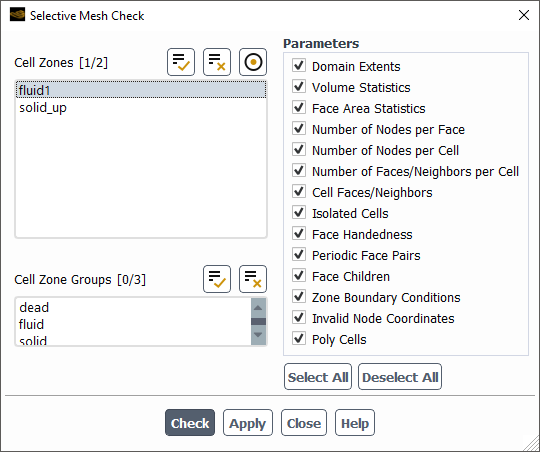
Select one or more cell zones from the Cell Zone list.
Alternatively, you can select one or more groups of cell zones from the Cell Zone Groups list.
From the Parameters group, select specific items from the list of available mesh checking categories, use the Select All or Deselect All buttons accordingly, or keep the default selection of all the items.
Domain Extents
Volume Statistics
Face Area Statistics
Number of Nodes per Face
Number of Nodes per Cell
Number of Faces/Neighbors per Cell
Cell Faces/Neighbors
Isolated Cells
Face Handedness
Periodic Face Pairs
Face Children
Zone Boundary Conditions
Invalid Node Coordinates
Poly Cells
Once the cell zone(s) and the parameters are selected, click the Check button to perform the selective mesh check, and view the output in the console window. The check is performed for the selected zone and the corresponding adjacent faces, including the interiors of the selected zone, as well as any corresponding edges.
You can perform a selective mesh check using the text user interface (TUI).
mesh/selective-mesh-check
The command will prompt you for one or more cell zones, as well as whether to include any of the mesh check parameters. For example:
Meshing/mesh> selective-mesh-check
Select one or more cell zones for the mesh check.
Available cell zone(s): (solid_up:232 fluid1)
()
Cell Zones(1) [()] fluid1
Cell Zones(2) [()]
Specify selective mesh check parameters:
Domain Extents? [yes] y
Volume Statistics? [yes] y
Face Area Statistics? [no] n
Number of Nodes per Face? [yes] n
Number of Nodes per Cell? [yes] n
Number of Faces/Neighbors per Cell? [no] n
Cell Faces/Neighbors? [no] n
Isolated Cells? [yes] n
Face Handedness? [yes] n
Periodic Face Pairs? [yes] n
Face Children? [yes] n
Zone Boundary Conditions? [yes] n
Invalid Node Coordinates? [yes] n
Poly Cells? [yes] n
Once the prompts are complete, the mesh check will proceed and display the results in the console window. For example, given the previous input example, the output would look like:
Mesh check for cell zone(s): (fluid1)
Domain extents.
  x-coordinate: min = -3.627150e+02, max = 1.345894e+01.
  y-coordinate: min = -1.250188e+02, max = 2.475194e-09.
  z-coordinate: min = -1.018144e+02, max = 1.343869e+01.
Volume statistics.
  minimum volume: 1.420005e-03.
  maximum volume: 2.548519e+02.
    total volume: 8.211535e+05.
Done.It is important to check the quality of the volume mesh to evaluate whether it is sufficient for the problem you are modeling. It is recommended that you check the mesh quality before transferring the mesh data to solution mode or writing out the mesh/case file.
You can obtain information about the volume mesh quality by selecting the Mesh/Check Quality menu item.
>
When you select > , the quality information will be printed in the console. The sample output is as follows:
Mesh Quality:

Minimum Orthogonal Quality = 4.37436e-01

Maximum Aspect Ratio = 1.66634e+02
Note: The quality reported corresponds to that reported using the button in the General task page in solution mode (refer to Mesh Quality for details).
For information about additional quality metrics, set the
/mesh/check-quality-level to 1 prior to
using the > option. In addition to the orthogonal quality and Fluent aspect ratio,
additional metrics such as cell squish and skewness will be reported when the
check-quality-level is set to 1.
If you are dissatisfied with the volume mesh generated, you can choose to clear the mesh and start again from the boundary mesh. When the mesh is cleared, all interior nodes and faces, and all cells both live and dead are deleted. Only the boundary nodes and faces will be left. After the mesh is cleared, you can generate a new mesh.
This feature is available via > .
You can also use the text command /mesh/clear-mesh. To delete
the boundary mesh, use the text command mesh/reset-mesh. When you
use either of these commands you will be asked to confirm that you want to clear or reset
the mesh.
Important: If you have used domains to generate the mesh or grouped zones for reporting (as described in Using Domains to Group and Mesh Boundary Faces), only the mesh in the active domain will be cleared.