


The following sections describe how to use the NOx models in Ansys Fluent. For information about the theory behind the NOx models in Ansys Fluent, see NOx Formation in the Theory Guide.
NOx concentrations generated in combustion systems are generally low. As a result, NOx chemistry has negligible influence on the predicted flow field, temperature, and major combustion product concentrations. It follows that the most efficient way to use the NOx model is as a postprocessor to the main combustion calculation.
The recommended procedure is as follows:
Calculate your combustion problem using Ansys Fluent as usual.
Important: The premixed combustion model is not compatible with the NOx model.
Important: If you plan to use the Ansys Fluent selective non-catalytic reduction (SNCR) model for NOx reduction, you must first include ammonia NH3 or urea CO(NH2)2 (depending upon which reagent is employed) as a fluid species in the main combustion calculation and define appropriate species injections, as described later in this section. See Defining the Species in the Mixture for details about adding species to your model and Setting Initial Conditions for the Discrete Phase for details about creating injections.
Enable the desired NOx models (thermal, prompt, fuel, and/or N2O intermediate NOx, with or without reburn), define the fuel streams (for prompt NOx and fuel NOx only), and set the appropriate parameters, as described in this section.
 Setup → Models → Species → NOx
  Edit...
Define the boundary conditions for NO (and HCN, NH3, or N2O if necessary) at flow inlets.
Setup →  Boundary Conditions
(steady state only) In the Equations Dialog Box, turn off the solution of all variables except species NO (and HCN, NH3, or N2O, based on the model selected).
Solution → Controls
→ Equations...
(transient cases only) In the Run Calculation task page, select Postprocess Pollutants and adjust Max Post Iterations/Time Step as needed.
Solution → Run
Calculation
Perform calculations until convergence (that is, until the NO—and HCN, NH3, or N2O, if solved—species residuals are below 10-6).
Solution → Run Calculation
Review the mass fractions of NO (and HCN, NH3, or N2O) by generating graphical plots or alphanumeric reports in the usual way.
Save a new set of case and data files, if desired.
 File → Write → Case & Data...
Inputs specific to the calculation of NOx formation are explained in the remainder of this section.
To enable the NOx models and set related parameters, you will use the NOx Model Dialog Box (for example, Figure 22.1: The NOx Model Dialog Box).
![]() Setup → Models → Species → NOx
Setup → Models → Species → NOx ![]() Edit...
Edit...
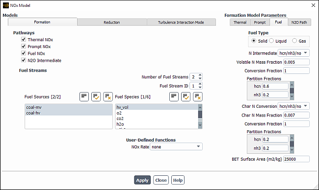
In the Formation tab, select the NOx models under Pathways to be used in the calculation of the NO and HCN, NH3, or N2O concentrations:
To enable thermal NOx, turn on the Thermal NOx option.
To enable prompt NOx, turn on the Prompt NOx option.
To enable fuel NOx, turn on the Fuel NOx option.
Important: When using the non-premixed combustion model, the following limitation exists for the Fuel NOx option:
The Fuel NOx option is only available if the DPM model is also enabled.
To enable the formation of NOx through N2O intermediate, turn on the N2O Intermediate option. (Note that the N2O option will not appear until you have enabled one of the other NO models listed above.)
Your selection(s) under Pathways will enable the calculation of thermal, prompt, fuel, and/or N2O-intermediate NOx in accordance with the chemical kinetic models described in Thermal NOx Formation through NOx Formation from Intermediate N2O in the Theory Guide. Mean NO formation rates will be computed directly from mean concentrations and temperature in the flow field.
When modeling fuel NOx formation, Ansys Fluent allows you to define up
to three separate fuel streams, and to select  fuel sources for each fuel stream.
You can define multiple fuel streams to include in your model with the following configurations:
Solid and liquid fuels (combusting particle and droplet) both contributing to fuel NOx.
Two or three solid fuels with different
 -content and NOx model parameters (two or three
combusting particles), for example coal blends, coal-biomass cofiring, and so on.
-content and NOx model parameters (two or three
combusting particles), for example coal blends, coal-biomass cofiring, and so on.Two or three liquid fuels with different
 -content and NOx model parameters (two or three
droplet or multicomponent particles).
-content and NOx model parameters (two or three
droplet or multicomponent particles).Gas and solid (or droplet) fuel both contributing to fuel NOx.
In addition, you can model one solid fuel contributing to NOx in the presence of another reacting solid particle not containing any
 (for example, sorbent injection in a coal furnace or calcination reaction
in cement kiln) by specifying the active
(for example, sorbent injection in a coal furnace or calcination reaction
in cement kiln) by specifying the active  fuel source for NOx formation. For this
configuration, you will not need to define multiple fuel streams in your model.
fuel source for NOx formation. For this
configuration, you will not need to define multiple fuel streams in your model.
If Fuel NOx is enabled in the Pathways group box in the Formation tab, perform the following steps to define multiple fuel streams:
Specify the Number of Fuel Streams in the Fuel Streams group box.
Note: You are allowed up to three separate fuel streams.
Define the first fuel stream.
Select the fuel stream to be defined by using the arrow keys of the Fuel Stream ID field.
Select the Fuel Type in the Fuel tab for the Formation Model Parameters.
If your Fuel Type is Liquid or Solid, select the N sources from the Fuel Sources list.
If the Fuel Type is Solid and you have defined multiple injections with different combusting particle materials in your reacting flow calculation, the available combusting particle materials will be listed in the Fuel Sources list. Select one or more materials from the list to be included as fuel sources in the Fuel NOx calculation. Your selection will be used to determine the char burnout rate
 and volatile release rate
  in the coal fuel NOx formation rate models
described in Fuel NOx from Coal in the Theory Guide. Make sure to deselect all
combusting particle materials that do not contribute to
NOx.
in the coal fuel NOx formation rate models
described in Fuel NOx from Coal in the Theory Guide. Make sure to deselect all
combusting particle materials that do not contribute to
NOx.If the Fuel Type is Liquid and you have defined multiple injections with different droplet or multicomponent particle materials in your reacting flow calculation, the available materials will be listed in the Fuel Sources list. Select one or more materials from the list to be included as fuel sources in the Fuel NOx calculation. Your selection will be used to determine the fuel release rate
 in the liquid fuel NOx formation rate models
described in Fuel NOx from Intermediate Hydrogen Cyanide (HCN) and Fuel NOx from Intermediate Ammonia (NH3) in the Theory Guide. Make sure to deselect all
droplet and multicomponent materials that do not contribute to
NOx.
in the liquid fuel NOx formation rate models
described in Fuel NOx from Intermediate Hydrogen Cyanide (HCN) and Fuel NOx from Intermediate Ammonia (NH3) in the Theory Guide. Make sure to deselect all
droplet and multicomponent materials that do not contribute to
NOx.
If you are also modeling Prompt NOx, select the fuel species from the Fuel Species list. You cannot select more than 5 fuel species for each fuel stream, and the total number of fuel species selected for all the fuel streams combined cannot exceed 10. You can define the same, or different Fuel Species, Fuel Carbon Number and Equivalence Ratio for each stream. The Fuel Carbon Number and Equivalence Ratio can be modified in the Prompt tab under Formation Model Parameters.
If the Fuel Type in your model is Gas, select one or more materials from the Fuel Species list. Your selection will be used to determine the mean limiting reaction rate
 in the gaseous fuel NOx formation rate models
described in Fuel NOx from Intermediate Hydrogen Cyanide (HCN) and Fuel NOx from Intermediate Ammonia (NH3) in the Theory Guide. If you are also modeling
Prompt NOx formation, the same fuel selection will apply also for the
prompt NOx model.
in the gaseous fuel NOx formation rate models
described in Fuel NOx from Intermediate Hydrogen Cyanide (HCN) and Fuel NOx from Intermediate Ammonia (NH3) in the Theory Guide. If you are also modeling
Prompt NOx formation, the same fuel selection will apply also for the
prompt NOx model.Set the other parameters associated with your selected pathway(s) in the Prompt and/or Fuel tabs under Formation Model Parameters. See Setting Prompt NOx Parameters and Setting Fuel NOx Parameters for details.
Repeat steps 2.(a)–2.(f) for each additional fuel stream.
Important:
The gaseous fuel option is available only when the species model is enabled.
Important considerations should be made when reading case and data files set up in a version of Ansys Fluent 14.5 or earlier:
When reading a case and data file with multiple injection materials that was set up in Ansys Fluent version 14.5 or earlier, Ansys Fluent will initialize the injection material specific fuel N sources for the fuel NOx model. Ansys Fluent will perform a DPM iteration when the flow iterations are initiated.
When reading a case file that was set up in a version older than Ansys Fluent 14.5 with multiple fuel streams defined for the Fuel NOx model, you must review the setup and select the N sources from the Fuel Sources list.
You can choose to specify a user-defined function for the rate of NOx production. By default, the rate returned from the UDF is added to the rate returned from the standard NOx production options, if any are selected. You also have the option of replacing any or all of Ansys Fluent’s NOx rate calculations with your own user-defined NOx rate.
In addition to or instead of using the UDF to specify the
NOx rate, you can use it to specify custom values for the maximum
limit ( ) that is used for the integration of the temperature PDF (when temperature is
accounted for in the turbulence interaction modeling).
) that is used for the integration of the temperature PDF (when temperature is
accounted for in the turbulence interaction modeling).
To use a UDF to add a rate to Ansys Fluent’s NOx rate calculations, you must compile and load the desired function, and then select it from the NOx Rate drop-down list in the User-Defined Functions group box in the Formation tab. After you have selected the UDF, you have the following options:
You can specify that your custom rate is added to the Ansys Fluent NOx rate calculations, by retaining the default selection of Add to Fluent Rate in the UDF Rate group box for the appropriate NOx formation pathway(s) (for example, in the Fuel tab).
You can replace the Ansys Fluent NOx rate calculations with your custom rate, by selecting Replace Fluent Rate in the UDF Rate group box for the appropriate NOx formation pathway(s) (for example, in the Fuel tab).
You can specify custom values for
 , by selecting user-defined from
the Tmax Option drop-down list in the Turbulence Interaction Mode tab.
, by selecting user-defined from
the Tmax Option drop-down list in the Turbulence Interaction Mode tab.
See the Fluent Customization Manual for details about user-defined functions.
The  routines employ three methods for calculation of thermal
NOx (as described in Method 1: Equilibrium Approach in the Theory
Guide). You will specify the method to be used in the Thermal
tab, under Formation Model Parameters in the NOx Model Dialog Box:
routines employ three methods for calculation of thermal
NOx (as described in Method 1: Equilibrium Approach in the Theory
Guide). You will specify the method to be used in the Thermal
tab, under Formation Model Parameters in the NOx Model Dialog Box:
To choose the equilibrium method, select equilibrium in the [O] Model drop-down list.
To choose the partial equilibrium method, select partial-equilibrium in the [O] Model or [OH] Model drop-down list.
To use the predicted O and/or OH concentration, select instantaneous in the [O] Model or [OH] Model drop-down list.
Important: Note that the urea model uses the [OH] model.
If you hooked a user-defined function in the Formation tab, you can make a selection in the UDF Rate group box to specify the treatment of the user-defined NOx rate:
Select Replace Fluent Rate to replace Ansys Fluent’s thermal NOx rate calculations with the custom NOx rate produced by your UDF.
Select Add to Fluent Rate to add the custom NOx rate produced by your UDF to Ansys Fluent’s thermal NOx rate calculations.
Prompt NOx formation is predicted using Equation 9–26 and Equation 9–28 in the Theory Guide. For each fuel stream specified in the Fuel Stream ID field in the Formation tab, set the parameters in the Prompt tab under Formation Model Parameters in the NOx Model Dialog Box in the following manner:

If you hooked a user-defined function in the Formation tab, you can make a selection in the UDF Rate group box to specify the treatment of the user-defined NOx rate:
Select Replace Fluent Rate to replace Ansys Fluent’s prompt NOx rate calculations with the custom NOx rate produced by your UDF.
Select Add to Fluent Rate to add the custom NOx rate produced by your UDF to Ansys Fluent’s prompt NOx rate calculations.
When using the fuel NOx model, you must set the parameters in the Fuel tab under Formation Model Parameters for each fuel stream specified in the Fuel Stream ID field in the Formation tab.
If you hooked a user-defined function in the Formation tab, you can make a selection in the UDF Rate group box to specify the treatment of the user-defined NOx rate:
Select Replace Fluent Rate to replace Ansys Fluent’s fuel NOx rate calculations with the custom NOx rate produced by your UDF.
Select Add to Fluent Rate to add the custom NOx rate produced by your UDF to Ansys Fluent’s fuel NOx rate calculations.
If there is no NOx rate UDF or if you selected Add to Fluent Rate, you must define fuel parameters. To begin, specify the fuel type in the following manner:
For solid fuel NOx, select Solid under Fuel Type.
For liquid fuel NOx, select Liquid under Fuel Type.
For gaseous fuel NOx, select Gas under Fuel Type.
Note that you can use only one of the fuel types for a given fuel stream. The Gas option is available only when the Species Transport model is enabled (see Enabling Species Transport and Reactions and Choosing the Mixture Material).
If you have selected Gas or Liquid as the Fuel Type, you must also specify the following:
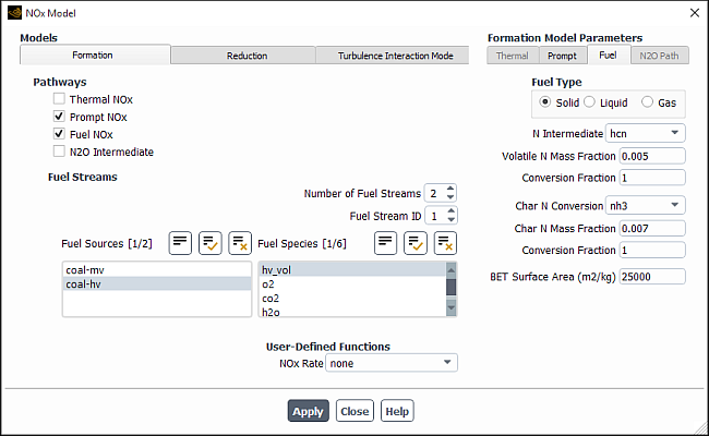
Select the intermediate species (hcn, nh3, or hcn/nh3/no) in the N Intermediate drop-down list.
Set the correct mass fraction of nitrogen in the fuel (kg nitrogen per kg fuel) in the Fuel N Mass Fraction field.
Specify the overall fraction of the fuel N, by mass, that will be converted to the intermediate species and/or product NO in the Conversion Fraction field. The Conversion Fraction for the N Intermediate has a default value of 1. Therefore, any remaining N will not contribute to NOx formation. This is based on the assumption that the remaining volatile N will convert to gas phase nitrogen. However, this has very little effect on the overall mass fraction of gas phase nitrogen. Therefore, you do not have to solve for nitrogen species when solving pollutant transport equations.
If you selected hcn/nh3/no as the intermediate, specify the fraction of the converted fuel N, by mass, that will become hcn and nh3 under Partition Fractions. The fraction of fuel N that will become NO will be calculated by the remainder.
Note that setting a partition fraction of 0 for both HCN and NH3 is equivalent to assuming that all fuel N is converted to the final product NO, whereas a partition fraction of 0 for HCN and 1 for NH3 is the same as selecting nh3 as the intermediate.
Ansys Fluent will use Equation 9–31 and Equation 9–32 in the Theory Guide (for HCN) or Equation 9–42 and Equation 9–43 in the Theory Guide (for NH3) to predict NO formation for a gaseous or liquid fuel.
Important: Note that there is a limitation that must be considered when defining more than one liquid fuel stream. See Defining the Fuel Streams for details.
For solid (coal) fuel, Ansys Fluent will use Equation 9–55 and Equation 9–56 in the Theory Guide (for HCN) or Equation 9–62 and Equation 9–63 in the Theory Guide (for NH3) to predict NO formation. Several inputs are required for the coal fuel NOx model as follows:
Select the intermediate species (hcn, nh3, or hcn/nh3/no) in the N Intermediate drop-down list.
Specify the mass fraction of nitrogen in the volatiles in the Volatile N Mass Fraction field.
Specify the overall fraction of the volatile
 , by mass, that will be converted to the intermediate species and/or
product NO in the Conversion Fraction field.
, by mass, that will be converted to the intermediate species and/or
product NO in the Conversion Fraction field.If you selected hcn/nh3/no as the volatile N intermediate, specify the fraction of the converted volatile N, by mass, that will become hcn and nh3 under Partition Fractions. The fraction of volatile N that will become NO will be calculated by the remainder.
Select the char N conversion path from the Char N Conversion drop-down list as no, hcn, nh3, or hcn/nh3/no. Note that hcn or nh3 can be selected only if the same species has been selected as the intermediate species in the N Intermediate drop-down list.
Specify the mass fraction of nitrogen in the char in the Char N Mass Fraction field.
Specify the overall fraction of the char N, by mass, that will be converted to the intermediate species and/or product NO in the Conversion Fraction field.
If you selected hcn/nh3/no as the char N conversion, specify the fraction of the converted char N, by mass, that will become hcn and nh3 under Partition Fractions. The fraction of char N that will become NO will be calculated by the remainder.
Define the BET internal pore surface area (see BET Surface Area in the Theory Guide for details) of the particles in the BET Surface Area field.
Important: Note that there are limitations that must be considered when defining more than one solid fuel stream. See Defining the Fuel Streams for details.
The following equations are used to determine the mass fraction of nitrogen in the volatiles and char:
 | (22–2) |
| where | |
 = release rate of fuel nitrogen in kg/s = release rate of fuel nitrogen in kg/s | |
 = release rate of volatiles ( = release rate of volatiles ( ) or char ( ) or char ( ) in kg/s ) in kg/s | |
 =
mass fraction of nitrogen in volatiles or char =
mass fraction of nitrogen in volatiles or char |
|
Let | |
|
| |
|
| |
|
| |
|
|


Then the following should hold:
 | (22–3) |
 | (22–4) |
 | (22–5) |
 | (22–6) |
 | (22–7) |
The formation of NO through an N2O intermediate can be predicted by any of quasi-steady and transported-simple methods, which can be specified in the N2O Path tab.
To choose the quasi-steady-state method, select quasi-steady in the N2O Model drop-down list.
Important: The transport equation for the species N2O will not be solved for N2O. However, N2O will be updated at every iteration. Therefore, the residual values that appear for N2O are always zero. Do not be alarmed if the solver keeps printing zero at each iteration.
To choose the simplified form of the N2O-intermediate mechanism, select transported-simple in the N2O Model drop-down list. Here, the species N2O is added to the list of pollutant species, and its mass fraction is solved via a transport equation.
The atomic O concentration will be calculated according to the thermal NOx [O] Model that you have specified previously. If you have not selected the Thermal NOx pathway, then you will be given the option to specify an [O] Model for the N2O pathway calculation. The same three options for the thermal NOx [O] Model will be the available options.
If you hooked a user-defined function in the Formation tab, you can make a selection in the UDF Rate group box to specify the treatment of the user-defined NOx rate:
Select Replace Fluent Rate to replace the NOx rate calculated by Ansys Fluent using N2O intermediates with the custom NOx rate produced by your UDF.
Select Add to Fluent Rate to add the custom NOx rate produced by your UDF to the NOx rate calculated by Ansys Fluent using N2O intermediates.
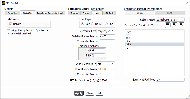
To enable NOx reduction by reburning, click the Reduction tab in the NOx Model Dialog Box and enable the Reburn option under Methods. In the expanded portion of the dialog box, as shown in Figure 22.3: The NOx Dialog Box Displaying the Reburn Reduction Method, click the Reburn tab under Reduction Method Parameters, where you can choose from the following options:
To choose the instantaneous method, select instantaneous [CH] in the Reburn Model drop-down list.
Important: When you use this method, you must be sure to include the species CH, CH2, and CH3 in your problem definition. See NOx Reduction by Reburning in the Theory Guide for details.
To choose the partial equilibrium method, select partial-equilibrium in the Reburn Model drop-down list. You then must select the Reburn Fuel Species from the list of available species. Ansys Fluent will allow you select up to six reburn fuel species. Specify the Equivalent Fuel Type (ch4, ch3, ch2, or ch). For example, if you choose methane as the reburn fuel, then the Equivalent Fuel Type would be ch4. If you choose a reburn fuel such as hv_vol (a volatile component of coal), then you must specify the most appropriate equivalent hydrocarbon fuel type so that the partial equilibrium model will be set up correctly.
Due to coal volatiles behaving very differently, it is important to select the correct equivalent fuel type. You must first consider the volatile fuel composition, then check the C/H ratio to find the fuel that most closely matches CH, CH2, CH3, or CH4 [90]. While the method for best determining the equivalent fuel is debatable, considering the C/H ratio of the fuel itself is a reasonable indicator.
Prior to enabling reduction by SNCR, make sure that you have included in the species list nh3 (for reduction by ammonia injection) and co<nh2>2 (for reduction by urea injection). See NOx Reduction by SNCR in the Theory Guide for detailed information about SNCR theory.
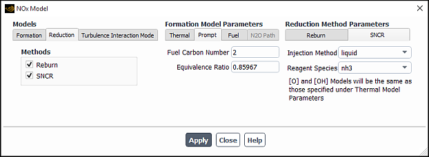
To enable NOx reduction by SNCR, click the Reduction tab in the NOx Model Dialog Box and enable the SNCR option under Methods, as shown in Figure 22.4: The NOx Dialog Box Displaying the SNCR Reduction Method.
In the SNCR tab under Reduction Method Parameters,set from the following options:
To have ammonia or urea included as a gas-phase pollutant species from the injection locations, select gaseous in the Injection Method drop-down list.
If you plan to select this option for NOx postprocessing, then you must also include ammonia or urea as a gas-phase species. Additionally, you must specify the mass fraction of ammonia or urea at the respective inlet for the SNCR injection. You must include this set of inputs prior to the main Ansys Fluent combustion calculation.
To have ammonia included as a liquid-phase pollutant species from the injection locations, select liquid in the Injection Method drop-down list. If urea is injected as a liquid solution, then select liquid in the Injection Method drop-down list. Note that you must enable the DPM model with urea or ammonia included as a material.
Note: All particle types such as droplets, combusting, and multicomponent particles are compatible with the SNCR model.
If you plan to select this option for NOx postprocessing, then you must include NH3 as both a gas-phase and liquid-phase species. Additionally, you must specify injection locations for liquid droplet ammonia particles and set gaseous ammonia as the evaporation species. You must include this set of inputs in conjunction with the main Ansys Fluent combustion calculation.
Since urea is a subliming solid, and usually is injected as a solution, mixed in water, you have to define solid properties for urea under the Create/Edit Materials Dialog Box. It is assumed that the water evaporates before urea begins its subliming process. The sublimation process is modeled similar to the single rate devolatilization model of coal. You will supply the value for the sublimation rate (s-1). You must specify the water content while defining the injection properties.
Specify the SNCR Reagent Species as nh3 (ammonia) or co<nh2>2 (urea) in the drop-down list.
When using the non-premixed combustion model with a liquid-phase reagent injection, enter a value in the Reagent Fraction in Stream to specify the mass fraction of the reagent in the reagent stream. The remaining mass fraction is assumed to be water. If you enabled a secondary stream in your PDF calculation, by default the secondary stream will act as the reagent stream. You can assign the primary stream as the reagent stream by using the text command that follows (enter
0in response to thePDF Stream IDprompt that follows theInjection Methodprompt):define/models/nox-parameters/nox-chemistryIf the Reagent Species selected is co <nh2> 2, then you will either accept the rate-limiting option for Urea Decomposition, or specify the NH3 Conversion value when selecting a user-specified Urea Decomposition.
You will use the urea decomposition under the SNCR tab to define which of the two decomposition models is to be used. The first model (which is the default) is the rate-limiting decomposition model, as given in Table 9.3: Two-Step Urea Breakdown Process in the Theory Guide. Ansys Fluent will then calculate the source terms according to the rates given in Table 9.3: Two-Step Urea Breakdown Process in the Theory Guide. The second model is for when you assume that the urea decomposes instantly into ammonia and HNCO at a given proportion. In this case, you will specify the molar conversion fraction for ammonia, assuming that the rest of the urea is converted to HNCO. An example value is given above.
The value for user-specified NH3 conversion is the mole fraction of NH3 in the mixture of NH3 and HNCO that is instantly created from the reagent injection. In this case, there is no urea source because all of reagent is assumed to convert to both NH3 and HNCO, instantly.
If you want to take into account turbulent fluctuations (as described in NOx Formation in Turbulent Flows in the Theory Guide) when you compute the specified NOx formation (thermal, prompt, and/or fuel, with or without reburn), define the turbulence parameters in the Turbulence Interaction Mode tab.
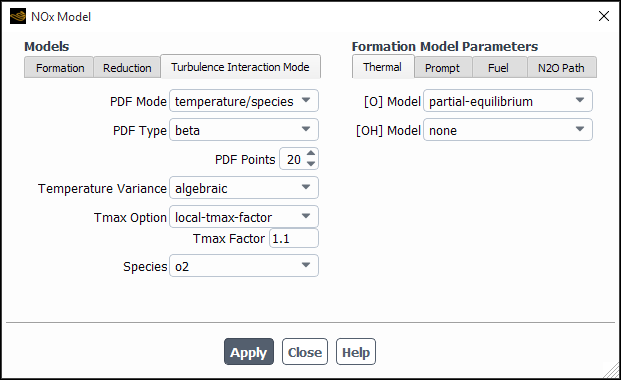
Select one of the options in the PDF Mode drop-down list in the Turbulence Interaction Mode tab:
Select temperature to take into account fluctuations of temperature.
Select temperature/species to take into account fluctuations of temperature and mass fraction of the species selected in the Species drop-down list (which appears when you select this option).
(non-premixed and partially premixed combustion calculations only) Select mixture fraction to take into account fluctuation in the mixture fraction(s).
Important: When modeling the formation of other pollutants along with NOx, you should compare the selections made in the PDF Mode drop-down lists in the Turbulence Interaction Mode group boxes of the NOx Model Dialog Box and the Turbulence Interaction Mode group box of the Soot Model dialog box. If mixture fraction is selected in any of these dialog boxes, then it must be selected in all of the others as well.
The mixture fraction option is available only if you are using either the non-premixed or partially premixed combustion model to model the reacting system. If you use the mixture fraction option, the instantaneous temperatures and species concentrations are taken from the PDF look-up table as a function of mixture fraction and enthalpy and the instantaneous NOx rates are calculated at each cell. The PDF used for convoluting the instantaneous NOx rates is the same as the one used to compute the mean flow-field properties. For example, for single-mixture fraction models the beta PDF is used, and for two-mixture fraction models, the beta or the double delta PDF can be used. The PDF for mixture fraction is calculated from the values of mean mixture fraction and variance at each cell, and the instantaneous NOx rates are convoluted with the mixture fraction PDF to yield the mean rates in turbulent flow.
Note: When mixture fraction is selected as PDF mode,
Ansys Fluent calculates and tabulates the NOx rates apriori for faster
computations of NOx rates. The NOx rates are
tabulated at the first NOx iteration and a message
Performing Pollutant PDF integrations...
is displayed in the Fluent console.
If you selected temperature or temperature/species for the PDF Mode, you should define the following parameters in the Turbulence Interaction Mode tab:
- PDF Type
allows you to specify the shape of the PDF, which is then integrated to obtain mean rates for the temperature and (if you selected temperature/species for the PDF Mode) the species. If you select beta, the PDF will be modeled using Equation 9–108 in the Theory Guide. If you select gaussian, the PDF will be modeled using Equation 9–111 in the Theory Guide.
- PDF Points
allows you to specify the number of points used to integrate the beta or Gaussian function in Equation 9–105 or Equation 9–106 in the Theory Guide on a histogram basis. The default value of 10 is a minimum value. It is recommended that you run the calculation with this minimum value to convergence, and then keep increasing the value (for example, 20–25) until the pollutants of interest stop changing. Increasing this value may improve accuracy, but will also increase the computation time.
- Temperature Variance
allows you to specify the form of transport equation that is solved to calculate the temperature variance. The default selection is algebraic, which is an approximate form of the transport equation (see Equation 9–114 of the Theory Guide). You also have the option of selecting transported to solve Equation 9–113 in the Theory Guide. Though the transported form is more exact, it is more expensive computationally.
- Tmax Option
provides various options for determining the maximum limit of the temperature used for the integration of the PDF (see Equation 8–44 in the Fluent Theory Guide) to calculate mean rates for turbulent fluctuations of NOx:
The default selection is global-tmax, which sets the limit as the maximum temperature in the flow field.
You can select local-tmax if you would rather obtain cell-based maximum temperature limits by multiplying the local cell mean temperature by the value entered in Tmax Factor.
You can select specified-tmax to set the limit for each cell to be the value entered in Tmax.
If you have selected a user-defined function in the NOx Rate drop-down list in the Formation tab, then you can select user-defined so that the temperature limit is specified by a user-defined function. See the Fluent Customization Manual for details about user-defined functions.
- Species
only appears if you have selected temperature/species for the PDF Mode. Your selection in this drop-down menu determines which species’ mass fraction is included in the NOx formation calculations.
Important: Note that the species variance will always be calculated using the algebraic form of the transport equation (Equation 9–114 in the Theory Guide).
At flow inlet boundaries, you must specify the Pollutant NO Mass Fraction, and if necessary, the Pollutant HCN Mass Fraction, Pollutant NH3 Mass Fraction, and Pollutant N2O Mass Fraction.
![]() Setup →
Setup → ![]() Boundary Conditions
Boundary Conditions
You can retain the default inlet values of zero for these quantities or you can enter nonzero numbers as appropriate for your combustion system.
To solve for NOx products, perform the following steps:
(optional) If the discrete phase model (DPM) is turned on (by enabling the Interaction with Continuous Phase) to run with the NOx model, then set the DPM Iteration Interval to
0such that no DPM iterations are performed as the NOx case is being solved.In the Equations Dialog Box of the Solution Controls Task Page, turn off the solution of all variables except species NO (and HCN, NH3, or N2O, based on the model selected).
- Solution →
Controls → Equations...
In the Solution Controls task page, set a suitable value for the NO (and HCN, NH3, or N2O, if appropriate) under-relaxation. A value of 1.0 is suggested, although lower values may be required for certain problems (that is, if convergence cannot be obtained, try a lower under-relaxation value).
In the Residual Monitors Dialog Box, decrease the convergence criterion for NO (and HCN, NH3, or N2O, if appropriate) to 10-6.
Solution → Monitors
→ Residuals Edit...
Perform calculations until convergence (that is, until the NO—and HCN, NH3, or N2O, if solved—species residuals are below 10-6) to ensure that the NO and HCN or NH3 concentration fields are no longer evolving.
Solution → Run
Calculation
When you compute NOx formation, the following additional variables will be available for postprocessing:
Mass fraction of Pollutant no
Mass fraction of Pollutant hcn (appropriate fuel NOx model only)
Mass fraction of Pollutant nh3 (appropriate fuel NOx model only)
Mass fraction of Pollutant n2o (N2O-intermediate model only)
Mass fraction of Pollutant urea (SNCR urea injection)
Mass fraction of Pollutant hnco (SNCR urea injection)
Mass fraction of Pollutant nco (SNCR urea injection)
Mole fraction of Pollutant no
Mole fraction of Pollutant hcn (appropriate fuel NOx model only)
Mole fraction of Pollutant nh3 (appropriate fuel NOx model only)
Mole fraction of Pollutant n2o (N2O-intermediate model only)
Mole fraction of Pollutant urea (SNCR urea injection)
Mole fraction of Pollutant hnco (SNCR urea injection)
Mole fraction of Pollutant nco (SNCR urea injection)
no Density
hcn Density (appropriate fuel NOx model only)
nh3 Density (appropriate fuel NOx model only)
n2o Density (N2O-intermediate model only)
urea Density (SNCR urea injection)
hnco Density (SNCR urea injection)
nco Density (SNCR urea injection)
Rate of no (from the individual pathways)
Rate of hcn (appropriate fuel NOx model only)
Rate of nh3 (appropriate fuel NOx model only)
Rate of n2o (N2O-intermediate model only)
Rate of urea (SNCR urea injection)
Rate of hnco (SNCR urea injection)
Rate of nco (SNCR urea injection)
RMS of Temperature (appropriate when either temperature or temperature/species is selected from the PDF Mode drop-down list in the NOx Model dialog box (Turbulence Interaction Mode tab)
These variables are contained in the NOx... category of the variable selection drop-down list that appears in postprocessing dialog boxes. Additional NO rates from individual pathways, Thermal, Prompt, Fuel, N2O Path, and SNCR can be plotted.