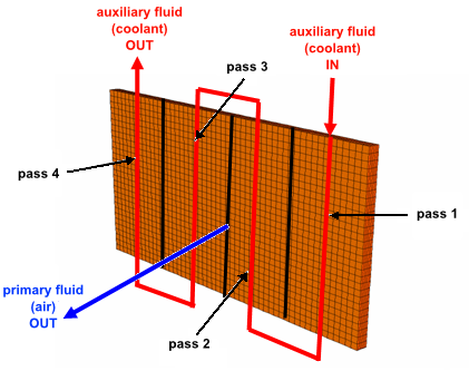
A heat exchanger consists of a primary fluid (for example, air) that comes into contact with one or more passes of an auxiliary fluid (for example, a coolant) that has a different temperature.
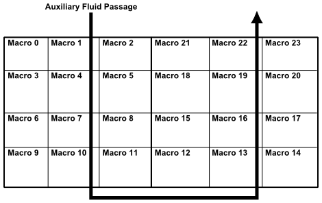
In a typical heat exchanger core, the auxiliary fluid temperature is stratified in the direction of the auxiliary fluid flow. As a result, heat rejection is not constant over the entire core. In Ansys Fluent, the fluid zone representing the heat exchanger core is subdivided into macroscopic cells or macros along the auxiliary fluid path, as in Figure 6.2: Core Discretized into 3x4x2 Macros. In this figure, the core is discretized into 3x4x2 macros. This configuration consists of two passes, each pass having four rows and three columns of macros. The auxiliary fluid inlet temperature to each macro is computed and then subsequently used to compute the heat rejection from each macro. This approach provides a realistic heat rejection distribution over the heat exchanger core.
To use the heat exchanger models, you must define one or more fluid zone(s) to represent the heat exchanger core. Typically, the fluid zone is sized to the dimension of the core itself. As part of the setup procedure, you will define the auxiliary fluid path, the number of macros, and the physical properties and operating conditions of the core (pressure drop parameters, heat exchanger effectiveness, auxiliary fluid flow rate, and so on).
You can also combine several fluid zones as a single heat exchanger group. In this situation each fluid zone acts as a separate heat exchanger core, and the auxiliary fluid mass flow rate of the heat exchanger group is divided among the zones in the ratio of the respective volumes. For the purpose of auxiliary fluid flow, heat exchanger groups can also be connected in series. In addition, a heat exchanger group can have an auxiliary fluid pressure drop (for example, for pressure dependent properties) and a supplementary auxiliary fluid stream entering or leaving it. For more information on heat exchanger groups, see Using the Grouped Macro Heat Exchanger Model.
The heat exchanger models were designed for “compact” heat exchangers, implying that the primary fluid side flow is unidirectional. The auxiliary fluid is assumed to flow through a large number of parallel tubes, which can optionally double back in a serpentine pattern to create a number of “passes”. You can independently choose the principal auxiliary fluid flow direction, the pass-to-pass direction and the external primary fluid flow direction.
Important: It is highly recommended that the free-form Tet mesh is not used in the macro heat exchanger model. Instead, evenly distributed Hex/Wedge cells should be used for improved accuracy and a more robust solution process.