


The thermal conductivity of a printed circuit board (PCB) varies considerably due to the layered construction and highly variable metal fraction at any particular location. Therefore, thermal analysis of a PCB requires knowledge of the orthotropic components of thermal conductivity (that is, X, Y, and Z components of thermal conductivity).
For the powermap distribution, Fluent uses SIWave DC IR drop analysis. DC IR Drop
analysis computes the joule heating losses and exports it into power map file
(.outb) for each conducting layer.
Ansys Fluent provides the PCB Model to automate the workflow, enabling the necessary case settings to prepare for thermal analysis of the PCB zones. This includes computing the orthotropic components of thermal conductivity and, by extension, the power distribution map of a PCB. This requires certain files from dependant on whether you are starting from an ECAD File or Board Configuration File.
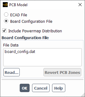
The PCB Model is initiated from Figure 16.89: The PCB Model Dialog Box:
![]() Physics → Model Specific
→ PCB Model...
Physics → Model Specific
→ PCB Model...
Note: Switching between the ECAD File-based and the Board Configuration File-based workflow results in reverting all PCB zones and settings. An informational dialog box appears to confirm this revert.
These two workflows and additional information are discussed below:
To compute the orthotropic thermal conductivity using an ECAD File, you must have the following files:
Electronic CAD mesh file
.aedb/edb.def(ECAD for Metal and di-electric layers, generated in ANSYS SIWave or ANSYS Electronic Desktop.)
Note: Currently supported materials for conducting layers in the
.aedb file are Cu-Pure and
copper and for dielectric layers in the
.aedb file, the supported materials are
FR-4, FR4_epoxy, and
air.
For the power distribution map, you also require:
SIWave Export Files (
.outb)
Important: The zone that is to be designated as PCB must be meshed using the Multizone meshing architecture of Fluent Meshing. Multizone meshing creates only hex cells while the surrounding fluid domain can be a poly or tet mesh. After multizone meshing is complete, the hex cells of the PCB zone will have non-conformal interfaces with the surrounding poly or tet cells. For details, see Adding Multizone Controls. After meshing, you can switch to Solution Mode to complete the rest of the PCB Model workflow described in this section.
Note: If you read both ECAD mesh and MCAD (mechanical) mesh, then the appropriate interfaces will need to be created between the two separate mesh zones.
After selecting ECAD File on the PCB Model dialog box, as shown in Figure 16.90: The PCB Model Dialog Box for ECAD File, the following steps are required to complete the PCB Model setup
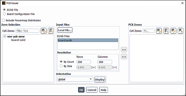
Under Zone Selection, all solid cell zones are listed. Any zone in this list are non-pcb zones. Select the zone(s) for which you would like to assign PCB settings.
Under Input Files, load an ECAD file (
.aedb/edb.def). Click Load File... to open a dialog box to read theedb.deffile. The.aedbfile will then appear in the ECAD Files field. Different ECAD files can be read for different cell zones. If you want to re-use an already loaded ECAD file, then you do not need to load it again, instead you can select it from the ECAD Files field for any other cell zone.Optionally you can Include Powermap Distribution that requires SIWave Export Files (
.outb) in the current working directory. These are binary files output by SIWave using the Export Icepak Power Map option from DC IR Drop Results in SIwave. A DC IR drop simulation in ANSYS SIWave generates power dissipation data for the copper layers.An extra field to specify the SIWave Export Files is exposed when Include Powermap Distribution is selected. Note that multiple SIWave export files can be selected.
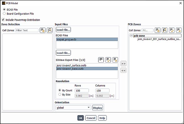
Under Resolution, you can specify By Count or By Size. The ECAD file can be thought of as an image and to generate the metal fraction, you need to obtain "pixelated" data from the file. You will need to provide details on the level of pixelation.
By Count - You provide the number of divisions along the length (Rows) and width (Columns) to divide the ECAD file.
By Size - You provide the size of each "pixel".
Under Orientation, you provide the local orientation of the PCB board. There is a drop-down menu where you can either select global as the local coordinate system if the origin of the PCB lies at (0,0,0) and is aligned along the coordinate axes, or you can select Create New to create a new reference frame. For details, see Reference Frames.
When any cell zone is selected and you click Create New, the Origin is pre-filled with the minimum node coordinates of the selected cell zone. Therefore, if you intend to create a local reference frame on the cell zone which should be centered at the minimum node coordinates and aligned along the X – Y plane, no further inputs are requires and you can click OK to create the reference frame.
You can also click Display to display the selected zone (pcb or non-pcb) along with the chosen reference frame. This can help to verify that the chosen reference frame is correctly aligned with the selected zone.
Click >> to designate the selected cell zone(s) a PCB Zone. The zone will now appear under PCB Zones. Note at any time, you can select a PCB zone from the list to see all the PCB settings associated with that zone.
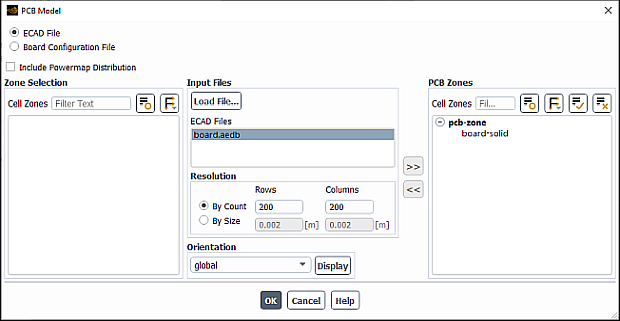
You can also select a PCB zone(s) and click << to revert all PCB settings for that zone. A dialog box will appear to confirm the revert. If accepted, the zone will move to the Cell Zones selection list.
Click OK and Fluent starts an automatic workflow from generating the metal fraction and board configuration files to determining the thermal conductivity map of the PCB and then interpolation of the conductivity map on to the CFD Mesh.
Fluent automatically creates a new solid material called
subst which can be viewed from the Materials list
in the outline view. By default, subst is assigned to
PCB cell zones.
![]() Setup → Materials
→ Solid →
subst
Setup → Materials
→ Solid →
subst
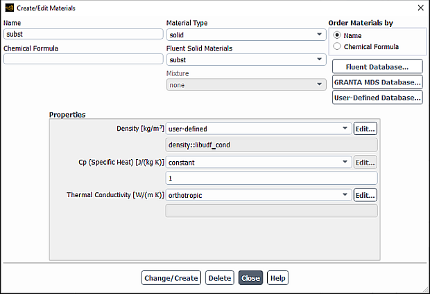
The material properties of subst are automatically defined:
Density is defined via UDF that is automatically set by the PCB model.
Specific heat is assigned a constant value of 1 because the density defined by the UDF is itself multiplied by the specific heat.
Thermal Conductivity is defined as
orthotropic. Clicking Edit... will open the Orthotropic Conductivity dialog box.
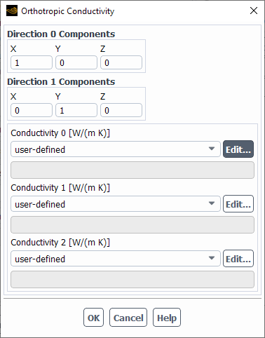
Conductivity 0, 1, and 2 are all automatically defined via UDF from the PCB model.
For more details on orthotropic conductivity, see Orthotropic Thermal Conductivity.
At this point, the case can be initialized and run.
Note: The PCB settings are preserved in the Fluent
.cas file and applied at run initialization.
Therefore, a case can be restarted without any accompanying ECAD or Board
Configuration files.
PCB Model Workflow with ECAD File Text Command
Use the command define/models/addon-module and enter
12 for the PCB Model.
You will be prompted to select from the menu as shown below. Enter
1 for the ECAD File workflow and follow the
prompts.
Read ECAD File.               (1)
Read Board Configuration File.(2)
Delete PCB Settings.          (3)

Choose an option from above. [1]
To compute the orthotropic thermal conductivity using a Board Configuration File, you must have the following files:
For the power distribution map, you also require:
Note: Each thread_id specified in the
board_config.dat file must match the PCB cell zone thread in
Fluent.
Note: If you read both ECAD mesh and MCAD (mechanical) mesh, then the appropriate interfaces will need to be created between the two separate mesh zones.
After selecting Board Configuration File on the PCB Model dialog box, as shown in Figure 16.93: The PCB Model Dialog Box for Board Configuration File, the following steps are required to complete the PCB Model setup
Optionally select Include Powermap Distribution if desired and ensure the appropriate
.profare available.Important: You must ensure that the appropriate
.proffiles are available in your working directory and are specified at the end of theboard_config.datfile. For example, if you have three powermap files (power-01.prof,power-02.prof,power-03.prof), the end of theboard_config.datshould read as follows:. . . power_prof=power-01.prof power-02.prof power-03.prof end Board 1
Fluent automatically loads and configures the appropriate files based on the board configuration file.
If needed, you can click Revert PCB Zones to revert all PCB settings for the affected zones. A dialog box will appear to confirm the revert.
Fluent automatically creates a new solid material
called subst which can be viewed from the Materials
list in the outline view. By default, subst is assigned
to PCB cell zones.
![]() Setup →
Materials → Solid
→ subst
Setup →
Materials → Solid
→ subst
The material properties of
subst are automatically defined:
Density is defined via UDF that is automatically set by the PCB model.
Specific heat is assigned a constant value of 1 because the density defined by the UDF is itself multiplied by the specific heat.
Thermal Conductivity is defined as
orthotropic. Clicking Edit... will open the Orthotropic Conductivity dialog box.
Conductivity 0, 1, and 2 are all automatically defined via UDF from the PCB model.
For more details on orthotropic conductivity, see Orthotropic Thermal Conductivity.
At this point, the case can be initialized and run.
Note: The PCB settings are preserved in the Fluent
.cas file and applied at run initialization.
Therefore, a case can be restarted without any accompanying ECAD or Board
Configuration files.
PCB Model Workflow with Board Configuration File Text Command
Use the command define/models/addon-module and enter
12 for the PCB Model.
You will be prompted to select from the menu as shown below. Enter
2 for the Board Configuration File workflow and
follow the prompts.
Read ECAD File.               (1)
Read Board Configuration File.(2)
Delete PCB Settings.          (3)

Choose an option from above. [2]
The following additional variables are available for postprocessing with the PCB model:
Note that these orthotropic thermal conductivities are computed in the global coordinate system.
Postprocessing Powermap Distribution
The powermap distribution can be postprocessed as any volumetric user energy source shown on the Flux Reports dialog box:
![]() Results → Reports
→ Fluxes...
Results → Reports
→ Fluxes...
On the Total Heat Transfer Rate flux report, the total powermap sources appear under User Source.
For more details, see Generating a Flux Report.