This chapter describes how to create and manage auxiliary geometry definitions, which can be useful for the following:
boundary adaption with the default polyhedral unstructured mesh adaption (PUMA) method (as described in Refining and Coarsening)
When performing PUMA adaption on a surface, you can specify that the new nodes that are created are projected onto a geometry definition, so that the resulting mesh better conforms to the geometry shape. For more information about the concept of geometry-based adaption, see Geometry-Based Adaption in the Theory Guide.
deforming dynamic mesh zones (as described in Deforming Motion)
You can specify that the nodes of the deforming mesh are projected onto an auxiliary geometry definition. This may simplify your setup, as the auxiliary geometry definitions provide shapes that are otherwise not available for deforming zones except through user-defined functions.
To manage auxiliary geometry, perform the following steps:
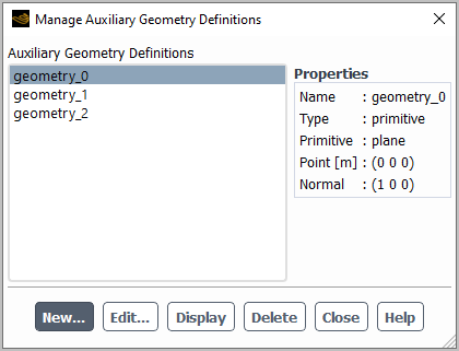
Open the Manage Auxiliary Geometry Definitions dialog box from the Outline View.
 Setup → Auxiliary Geometry
Definitions
Setup → Auxiliary Geometry
Definitions Manage...
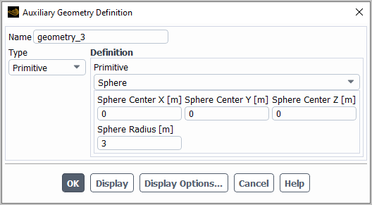
 Click the button in the Manage Auxiliary Geometry Definitions dialog box to open the Auxiliary Geometry Definition dialog box.
Enter a suitable Name for the definition.
Make a selection from the Type drop-down list to specify how you will define the geometry. You have the following options:
Primitive
This allows you to make a selection from the Primitive drop-down list in the Definition group box. You can choose to define the geometry as a Cone, Plane, Sphere, Frustum (of a cone), or Cylinder. Then you must define the geometry using the other settings in the Definition group box.
Note:For the Frustum definition, the Lower Radius is defined for the end at the Frustum Origin coordinates, and the Upper Radius is defined for the opposite end.
The geometry definition for the Frustum and Cylinder only includes the curved surfaces, that is, it does not include the circular planar faces on the ends. To create a geometry definition for the ends, you would need to create additional definitions of Plane primitives.
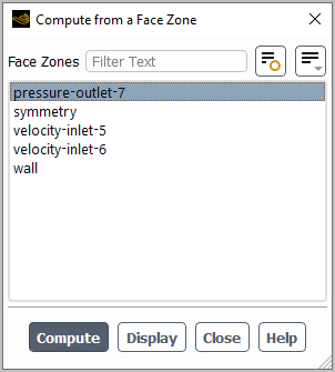
For the Plane definition, an easy way to define it is to click the button; then in the Compute from a Face Zone dialog box that opens, select a face zone that is planar from the list and click the button, and the fields in the Auxiliary Geometry Definition will be automatically filled. Note that after you select a zone in the Compute from a Face Zone dialog box, you have the option of clicking the button to verify that you have selected the intended zone.
User-Defined
This allows you to define the geometry by a user-defined function (UDF) that you have previously compiled. Select the UDF from the Function drop-down list in the Definition group box. Note that the UDF must use the
DEFINE_GEOMETRYmacro, as described inDEFINE_GEOMETRYin the Fluent Customization Manual.Surface Mesh
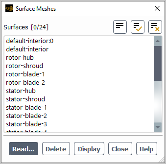
This allows you to define the geometry using a surface zone from a separate mesh file. Click the button; then in the Surfaces Meshes dialog box that opens, click the button, select a case, mesh, or STL file in the Select File dialog box that opens (being sure to select the units that the Mesh was created in), and close the Surfaces Meshes dialog box. Finally, specify the surface zone you want to define the geometry by making a selection from the Background Mesh drop-down in the Auxiliary Geometry Definition dialog box. For more information about reading surface meshes, see Reading Surface Mesh Files.
Reconstruction
This allows you to define the geometry using a reconstruction of the one or more boundary zones selected in the Face zones list in the Definition group box. This reconstruction represents the geometry by building a smooth background model based on the current node coordinates. If you want to maintain sharp feature edges where two boundary zones meet, you should ensure that the boundary zones are in separate geometry definitions (otherwise the edge may be smoothed / rounded in the reconstruction).
Note: Auxiliary geometry definitions of the Reconstruction type cannot be used in a deforming dynamic mesh zone when remeshing is enabled.
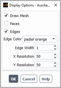
You can verify that your geometry is appropriately defined by clicking the button and viewing it in the graphics window. If necessary, you can alter how it is displayed by clicking the button and revising the setup in the Display Options - Auxiliary Geometry Definitions dialog box that opens.
The settings for the Display Options - Auxiliary Geometry Definitions dialog box are the following:
Draw Mesh
toggles the ability to draw the mesh at the same time that the geometry definition is displayed. Enabling this option opens the Mesh Display Dialog Box, which allows you to select the desired surface or zone meshes to be displayed.
Faces
enables the display of shaded faces for the geometry definition. The color of the faces are specified using the Face Color drop-down list.
Edges
enables the display of edges for the geometry definition. The color of the edges are specified using the Edge Color drop-down list, and the thickness of the edges is specified through the Edge Thickness field.
X Resolution and Y Resolution
These set the number of faces into which the curved surface of a primitive shape is discretized; higher values results in a higher resolution. The X Resolution defines the discretization along the length direction or (for a Sphere) the z-direction, while the Y Resolution defines it around the circumference or (for a Sphere) the longitude.
Click to save your settings and close the Auxiliary Geometry Definition dialog box.
Repeat the previous step to add additional auxiliary geometry definitions.
After you have created auxiliary geometry definitions, you can use the Manage Auxiliary Geometry Definitions dialog box to take further actions. If you select a definition from the Auxiliary Geometry Definitions list, details are displayed under Properties. You can then take the following actions:
To revise the selected definition, click the button and change the setup using the Auxiliary Geometry Definition dialog box that opens.
To display the selected definition in the graphics window, click the button.
To delete the selected definition, click the button.