


As an unstructured solver, Ansys Fluent uses internal data structures to assign an order to the cells, faces, and grid points in a mesh and to maintain contact between adjacent cells. Therefore, it does not require i,j,k indexing to locate neighboring cells. This gives you the flexibility to use the best mesh topology for your problem, as the solver does not force an overall structure or topology on the mesh.
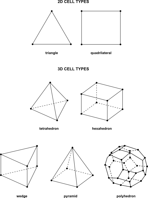
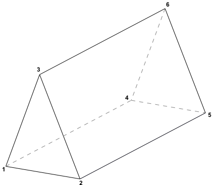
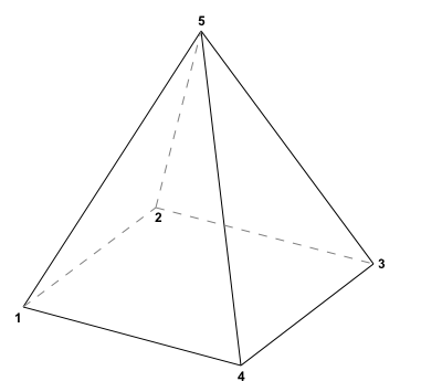
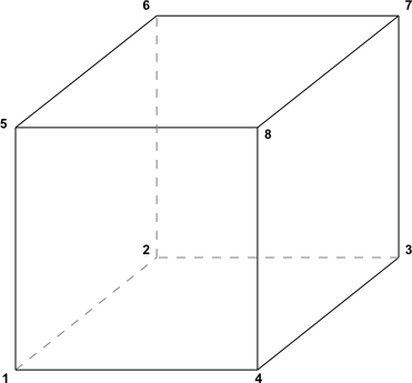
For 2D meshes, quadrilateral and triangular cells are accepted, and for 3D meshes, hexahedral, tetrahedral, pyramid, wedge, and polyhedral cells can be used. Figure 6.1: Cell Types depicts each of these cell types. Both single-block and multi-block structured meshes, as well as hybrid meshes containing quadrilateral and triangular cells or hexahedral, tetrahedral, pyramid, and wedge cells are acceptable. Ansys Fluent also can accept meshes with hanging nodes (that is, nodes on edges and faces that are not vertices of all the cells sharing those edges or faces) and hanging edges (that is, edges on faces that do not act as edges for both of the cells sharing those faces). While such hanging nodes / edges can be accepted, in 3D cases by default the adjacent cells are automatically converted to polyhedra when read to remove them; if you opt to disable this conversion, you must ensure that the hanging nodes / edges are removed from interior walls. See Hanging Node Adaption in the Theory Guide for information about acceptable hanging nodes, and Removing Hanging Nodes / Edges and Converting Cells with Hanging Nodes / Edges to Polyhedra for details on removing hanging nodes / edges. Meshes with non-conformal boundaries (that is, meshes with multiple subdomains in which the mesh node locations at the internal subdomain boundaries are not identical) are also acceptable. For details, see Non-Conformal Meshes.
Some examples of meshes that are valid for Ansys Fluent are presented in Examples of Acceptable Mesh Topologies. Different cell shapes and their face-node connectivity are explained in Face-Node Connectivity in Ansys Fluent. Choosing the Appropriate Mesh Type explains how to choose the mesh type that is best suited for your problem.
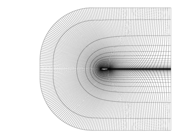
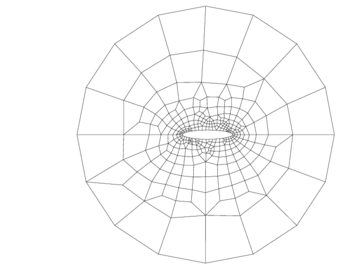
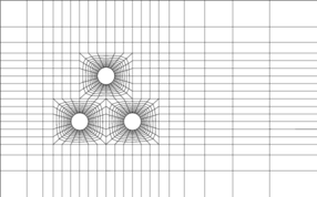
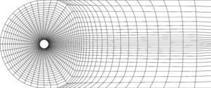
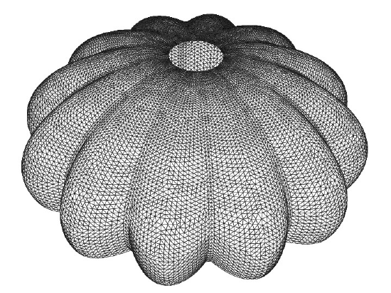
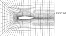
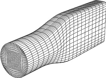
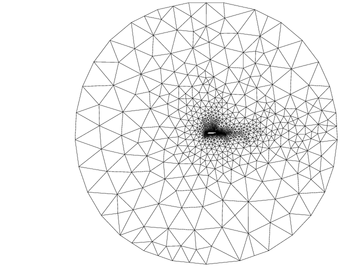
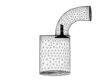
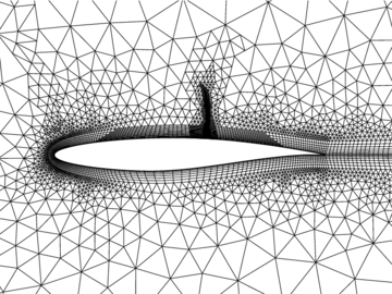
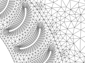
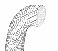
Ansys Fluent can solve problems on a wide variety of meshes. Figure 6.2: Structured Quadrilateral Mesh for an Airfoil-Figure 6.13: Polyhedral Mesh show examples of meshes that are valid for Ansys Fluent.
O-type meshes, meshes with zero-thickness walls, C-type meshes, conformal block-structured meshes, multiblock structured meshes, non-conformal meshes, and unstructured triangular, tetrahedral, quadrilateral, hexahedral, and polyhedral meshes are all acceptable.
Note: Though Ansys Fluent does not require a cyclic branch cut in an O-type mesh, it will accept a mesh that contains one.
This section contains information about the connectivity of faces and their related nodes in terms of node number and face number.
Face-node connectivity for the following cell shapes is explained here:
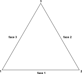
triangular (Figure 6.14: Face and Node Numbering for Triangular Cells)
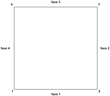
quadrilateral (Figure 6.15: Face and Node Numbering for Quadrilateral Cells)
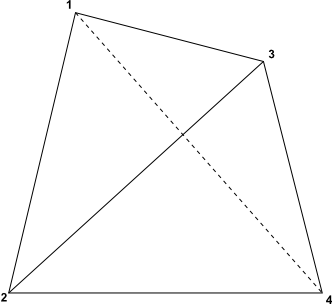
tetrahedral (Figure 6.16: Face and Node Numbering for Tetrahedral Cells)
wedge (Figure 6.17: Face and Node Numbering for Wedge Cells)
pyramidal (Figure 6.18: Face and Node Numbering for Pyramidal Cells)
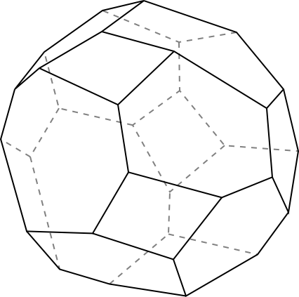
polyhedral (Figure 6.20: An Example of a Polyhedral Cell)
This information is useful in interfacing with Ansys Fluent.
Ansys Fluent can use meshes composed of triangular or quadrilateral cells (or a combination of the two) in 2D, and tetrahedral, hexahedral, polyhedral, pyramid, or wedge cells (or a combination of these) in 3D. The choice of which mesh type to use will depend on your application. When choosing mesh type, consider the following issues:
setup time
computational expense
numerical diffusion
Many flow problems solved in engineering practice involve complex geometries. The creation of structured or block-structured meshes (consisting of quadrilateral or hexahedral elements) for such problems can be extremely time-consuming if not impossible. Therefore, setup time for complex geometries is the major motivation for using unstructured meshes employing triangular or tetrahedral cells. However, if your geometry is relatively simple, there may be no saving in setup time with either approach.
Other risks of using structured or block-structured meshes with complicated geometries include the oversimplification of the geometry, mesh quality issues, and a less efficient mesh distribution (for example, fine resolution in areas of less importance) that results in a high cell count.
If you already have a mesh created for a structured code, it will save you time to use this mesh in Ansys Fluent rather than regenerate it. This can be a motivation for using quadrilateral or hexahedral cells in your Ansys Fluent simulation.
Note: Ansys Fluent has a range of filters that allow you to import structured meshes from other codes, including FLUENT 4. For details, see Mesh Sources.
When geometries are complex or the range of length scales of the flow is large, a triangular/tetrahedral mesh can be created with far fewer cells than the equivalent mesh consisting of quadrilateral/hexahedral elements. This is because a triangular/tetrahedral mesh allows clustering of cells in selected regions of the flow domain. Structured quadrilateral/hexahedral meshes will generally force cells to be placed in regions where they are not needed. Unstructured quadrilateral/hexahedral meshes offer many of the advantages of triangular/tetrahedral meshes for moderately-complex geometries.
A characteristic of quadrilateral/hexahedral elements that might make them more economical in some situations is that they permit a much larger aspect ratio than triangular/tetrahedral cells. A large aspect ratio in a triangular/tetrahedral cell will invariably affect the skewness of the cell, which is undesirable as it may impede accuracy and convergence. Therefore, if you have a relatively simple geometry in which the flow conforms well to the shape of the geometry, such as a long thin duct, use a mesh of high-aspect-ratio quadrilateral/hexahedral cells. The mesh is likely to have far fewer cells than if you use triangular/tetrahedral cells.
Converting the entire domain of your (tetrahedral) mesh to a polyhedral mesh will result in a lower cell count than your original mesh. Although the result is a coarser mesh, convergence will generally be faster, possibly saving you some computational expense.
In summary, the following practices are generally recommended:
For simple geometries, use quadrilateral/hexahedral meshes.
For moderately complex geometries, use unstructured quadrilateral/hexahedral meshes.
For relatively complex geometries, use triangular/tetrahedral meshes with wedge elements in the boundary layers.
For extremely complex geometries, use pure triangular/tetrahedral meshes.
A dominant source of error in multidimensional situations is numerical diffusion (false diffusion). The term false diffusion is used because the diffusion is not a real phenomenon, yet its effect on a flow calculation is analogous to that of increasing the real diffusion coefficient.
The following comments can be made about numerical diffusion:
Numerical diffusion is most noticeable when the real diffusion is small, that is, when the situation is convection-dominated.
All practical numerical schemes for solving fluid flow contain a finite amount of numerical diffusion. This is because numerical diffusion arises from truncation errors that are a consequence of representing the fluid flow equations in discrete form.
The second-order and the MUSCL discretization scheme used in Ansys Fluent can help reduce the effects of numerical diffusion on the solution.
The amount of numerical diffusion is inversely related to the resolution of the mesh. Therefore, one way of dealing with numerical diffusion is to refine the mesh.
Numerical diffusion is minimized when the flow is aligned with the mesh.
This is the most relevant to the choice of the mesh. If you use a triangular/tetrahedral mesh, the flow can never be aligned with the mesh. If you use a quadrilateral/hexahedral mesh, this situation might occur, but not for complex flows. It is only in a simple flow, such as the flow through a long duct, in which you can rely on a quadrilateral/hexahedral mesh to minimize numerical diffusion. In such situations, it is advantageous to use a quadrilateral/hexahedral mesh, since you will be able to get a better solution with fewer cells than if you were using a triangular/tetrahedral mesh.
If you would like higher resolution for a gradient that is perpendicular to a wall, you can create prism layers with higher aspect ratios near the wall.