You can create multiple local reference frames for use in setting up Ansys Fluent cases.
The reference frames feature allows you to create local coordinate systems with a given position and orientation, either with or without motion. Without local reference frames, you would have to specify things such as surfaces based on the global reference frame/coordinate system.
To create a reference frame:
Open the Reference Frame dialog box by right-clicking Reference Frames in the outline view and selecting New....
 Setup → Reference Frames
 New...
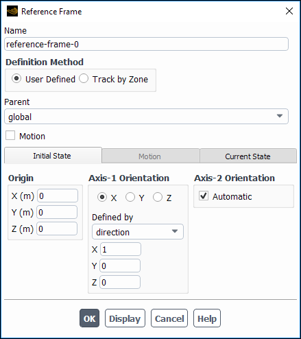
Enter a Name for the reference frame.
Specify how you want to define the reference frame.
User Defined allows you to completely specify the details of where the reference frame is located and oriented and how it moves.
Track by Zone allows you to "attach" a reference frame to a cell zone. You can still specify where the reference frame is located and how it is oriented, but you cannot specify any motion. If the zone it is tracking moves, so does the reference frame.
Specify either the Parent reference frame (when you select User Defined) or the Zone that the reference frame will track (when you select Track by Zone).
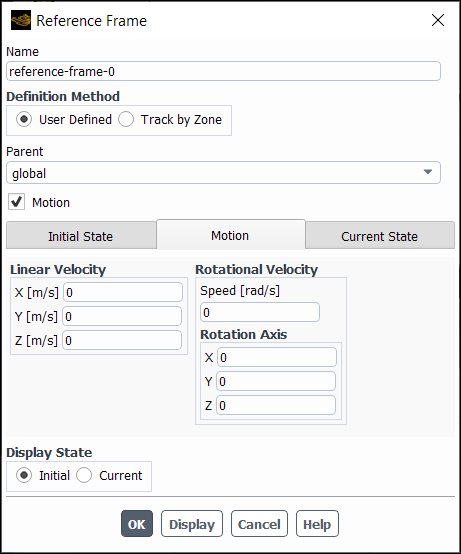
(Optional, User Defined only) enable Motion and specify the additional settings that appear in the Motion tab.
Linear Velocity is the linear velocity with respect to the parent reference frame orientation.
Rotational Velocity is the rotational velocity with respect to the parent reference frame orientation.
Specify the Origin of your reference frame.
Specify the orientation of the first axis of your reference frame in the Axis-1 Orientation group box. Select which axis you are specifying using by selecting either X, Y, or Z. You can either specify the orientation by providing a point or a direction.
(Optional) Specify the orientation of the second axis of your reference frame. By default, Fluent automatically provides an orientation for the second axis, but you can specify it manually by disabling Automatic and providing your own inputs.
Click to create the reference frame.
The Current State field shows you the current origin and axes directions of the reference frame with respect to the global reference frame.
Using Reference Frames
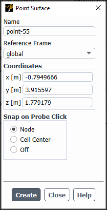
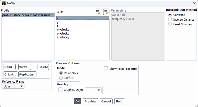
You can use any local reference frame when defining point surfaces and profiles. Just select the desired reference frame from the Reference Frame drop-down in the Point Surface or Profile dialog boxes.