


Contact element CONTA177 follows the contact pair concept used by the surface-to-surface elements (CONTA172 and CONTA174). You must pair CONTA177 with 3D target line segments (TARGE170) to model 3D beam-to-beam contact. See Identifying Contact Pairs for more information. CONTA177 uses most of the same element KEYOPTs and real constants as the surface-to-surface contact elements. Any differences are described in the next section.
The basic steps for performing a 3D beam-to-beam contact analysis are the same as those used for a typical surface-to-surface analysis. See Steps in a Contact Analysis for details.
Use the ESURF command to generate CONTA177 elements between corresponding contact pairs. This procedure is similar to that used for the surface-to-surface contact elements. If the underlying elements of target element TARGE170 are part of shell edges, use ESURF,,,LINE to generate 3D line or parabola target segments.
When using the line segments to form the target surface or using line-to-line contact elements to form the contact surface, the nodes must be entered in a sequence that defines a continuous line, as shown in the figure below.
The line can be made up of linear or parabolic segments, depending on whether the attached beam is made up of first order or second order elements. If the nodal ordering of the underlying beam elements is not consistent, you must either change them by reversing the node number order of the selected elements (ESURF,,REVERSE command) or make a consistent element ordering (ENORM command).
You can list the CONTA177 results using the PRESOL,CONT or PRETAB commands. Since CONTA177 is a 3D line element, you can also use the PLLS command to display element table items.
The following table shows the various contact (CONT) result items available via the PLNSOL and PLESOL commands.
| CONT | STAT | Contact status[1]:
| ||||
| " | PENE | Contact penetration | ||||
| " | PRES[2] | Contact pressure | ||||
| " | SFRIC[2] | Contact friction stress | ||||
| " | STOT[2] | Contact total stress (pressure plus friction) | ||||
| " | SLIDE | Contact sliding distance | ||||
| " | GAP | Contact gap distance | ||||
| " | CNOS | Total number of contact status changes during substep |
For MPC-based contact definitions, the value of STAT can be negative. This indicates that one or more contact constraints were intentionally removed to prevent over-constraint. STAT = -3 is used for MPC bonded contact. STAT = -2 is used for MPC no-separation contact.
For the contact force-based model (used for CONTA177 with KEYOPT(3) = 0 or 4), PRES, SFRIC, and STOT are the contact normal force, contact friction force, and total contact force, respectively.
CONTA177 uses most of the same KEYOPTs that are used by the surface-to-surface contact elements, CONTA172 and CONTA174. KEYOPT(3), KEYOPT(4), and KEYOPT(14) differ from the other contact elements, and KEYOPT(11) is not used by CONTA177 for beam-to-beam contact. See Element KEYOPTS for a listing of the remaining KEYOPTs.
CONTA177 uses the same real constants used by the surface-to-surface contact elements (CONTA172 and CONTA174), except for the units of FKN and FKT. See a listing of the real constants in Real Constants.
For beam-to-beam contact, an important assumption is that of constant circular beam cross section. The contact radius is assumed to be the same for all CONTA177 elements in the contact pair. Likewise, the target radius is assumed to be the same for all TARGE170 elements in the contact pair. You supply the target and contact radii through real constants R1 and R2, respectively.
For a general beam cross section, you can use an equivalent circular beam in the contact definition (see figure below). Use these guideline to define the equivalent circular cross section:
Determine the smallest cross section along the beam axis.
Determine the largest circle embedded in that cross section.

Use the first real constant, R1, to define the radius on the target side (target radius rt). Use the second real constant, R2, to define the radius on the contact side (contact radius rc).
To model external contact between the exterior surfaces of two cylindrical beams, set KEYOPT(9) = 0 (default) for the TARGE170 target elements in the contact pair. To model internal contact (a beam or pipe sliding within another beam or pipe), set KEYOPT(9) = 1 for the TARGE170 elements and input R1 as the inner radius of the outer beam.
In a general contact definition, the equivalent beam radius is specified via SECTYPE and SECDATA commands instead of using real constants. For more information, see the discussion on applying surface geometry in a general contact definition.
For both pair-based contact and general contact, if the contact radius and/or target radius are not defined, the program automatically calculates the equivalent radius for each individual contact/target element based on the associated geometry of underlying elements. In this case, the equivalent radius may vary within a contact pair or within a general contact surface.
In the case of a rigid target defined with TARGE170 elements, the program cannot calculate an equivalent radius because there are no underlying elements. Therefore, you must explicitly input the target radius for all rigid target elements.
For beam-to-beam contact, the thickness effect is accounted for through the contact and target radii. Therefore, KEYOPT(11), which controls the thickness effect for line-to-surface contact, is not used.
For CONTA177, KEYOPT(3) determines the type of 3D beam-to-beam contact as follows:
Use KEYOPT(3) = 0 or 1 to model contact between parallel beams
Use KEYOPT(3) = 3 or 4 to model contact between beams that cross.
Use KEYOPT(3) = 2 to model contact between parallel beams and/or contact between beams that cross.
KEYOPT(9) of the target element (TARGE170) determines whether you are modeling external contact between beams (KEYOPT(9) = 0, default) or internal contact between beams (KEYOPT(9) = 1). Internal contact can be a beam inside a hollow beam or a pipe inside a pipe.
KEYOPT(3) also allows you to choose between a contact force-based model (KEYOPT(3) = 0 or 4), and a contact traction-based model (KEYOPT(3) = 1, 2, or 3). For the contact traction-based model, the program determines the area (based on beam element length and the contact radius, R2) associated with the contact node.
When the traction-based model is specified, certain real constants (FKN, FKT, TNOP) and postprocessing items (PRES, TAUR, TAUS, SFRIC, and so on) have the same units as in the surface-to-surface contact elements (CONTA172 and CONTA174).
When the force-based model is specified, the units of these quantities have a factor of AREA with respect to those used in the traction-based model. For example, contact stiffness FKN has units FORCE/LENGTH for the force-based model, but FORCE/LENGTH3 for the traction-based model. PRES is the contact normal force in the force-based model, but contact pressure in the traction-based model. See the CONTA177 element description for detailed information on the units for these quantities.
For CONTA177, the contact normal is uniquely defined and is perpendicular to both the contact and the target surfaces (two contacting beams). Real constant TOLS is used to add a small tolerance that will internally extend the edge of the target surface. TOLS is useful for problems where contact nodes are likely to lie on the edge of the target (as at symmetry planes or for models generated in a node-to-node contact pattern). In these situations, the contact node may repeatedly slip off the target surface and be completely out of contact, resulting in convergence difficulties from oscillations.
Units for TOLS are percent (1.0 implies a 1.0% increase in the target edge length). A small value of TOLS will usually prevent this situation from occurring. The default value is 2 for both small deflection (NLGEOM,OFF) and large deflection (NLGEOM,ON).
You can use CONTA177 with the multipoint constraint (MPC) approach (KEYOPT(2) = 2) to define surface-based constraints. The KEYOPT(4) setting determines the type of surface-based constraint (rigid surface, force-distributed, or coupling constraint).
Note that in the case of collinear nodes, the moment along the axes parallel to the collinear nodes cannot be transmitted.
For the force-distributed constraint and the rigid surface constraint, you can use the Lagrange multiplier method (KEYOPT(2) = 3) as an alternative to the MPC approach.
See Surface-based Constraints for more information.
Note: For beam-to-surface contact, KEYOPT(4) = 3 can be used to define the contact detection algorithm (see KEYOPT(4) in Line-to-Surface Contact (Pair-Based)). This options is not valid for beam-to-beam contact.
KEYOPT(14) allows each contact detection point to interact with multiple target segments simultaneously:
KEYOPT(14) = 0: each contact detection point can interact with only one target segment
KEYOPT(14) = 1: each contact detection point can interact with up to four target segments
KEYOPT(14) = 2: each contact detection point can interact with up to eight target segments
The maximum number of contact interactions allowed at each contact detection point is determined by the KEYOPT(14) and KEYOPT(3) settings, as outlined in the table below.
Table 5.1: Number of Interactions Allowed at Contact Detection Points
| KEYOPT(14) | Parallel or Crossing Beams | KEYOPT(3) | Model | Contact Interactions at Nodes I, J, and K [1] | Contact Interactions at Intersection Point (IP) on a Crossing Beam Element [2] |
|---|---|---|---|---|---|
| KEYOPT(14) = 0 | Parallel beams |
KEYOPT(3) = 0 KEYOPT(3) = 1 |
Force-based Traction-based | 1 | 0 |
| All beam scenarios |
KEYOPT(3) = 2 |
Traction-based | 1 | 1 | |
| Crossing beams |
KEYOPT(3) = 3 KEYOPT(3) = 4 |
Traction-based Force-based | 0 | 1 | |
| KEYOPT(14) = 1 | Parallel beams |
KEYOPT(3) = 0 KEYOPT(3) = 1 |
Force-based Traction-based | 4 maximum | 0 |
| All beam scenarios |
KEYOPT(3) = 2 |
Traction-based | 4 maximum | 4 maximum | |
| Crossing beams |
KEYOPT(3) = 3 KEYOPT(3) = 4 |
Traction-based Force-based | 0 | 4 maximum | |
| KEYOPT(14) = 2 | Parallel beams |
KEYOPT(3) = 0 KEYOPT(3) = 1 |
Force-based Traction-based | 8 maximum | 0 |
| All beam scenarios |
KEYOPT(3) = 2 |
Traction-based | 8 maximum | 8 maximum | |
| Crossing beams |
KEYOPT(3) = 3 KEYOPT(3) = 4 |
Traction-based Force-based | 0 | 8 maximum |
The following example models show different combinations of KEYOPT(14) and KEYOPT(3).
Figure 5.7: Using KEYOPT(14)
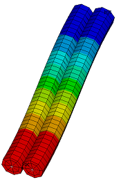 | 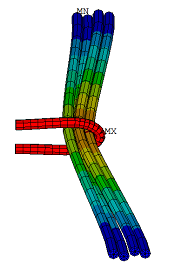 |
| KEYOPT(14) = 0 with Parallel Beams (KEYOPT(3) = 1) | KEYOPT(14) = 1 with Parallel and Crossing Beams (KEYOPT(3) = 2) |
 | 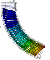 |
| KEYOPT(14) = 2 with Parallel Beams (KEYOPT(3) = 1) | KEYOPT(14) = 2 with Crossing Beams (KEYOPT(3) = 2) |