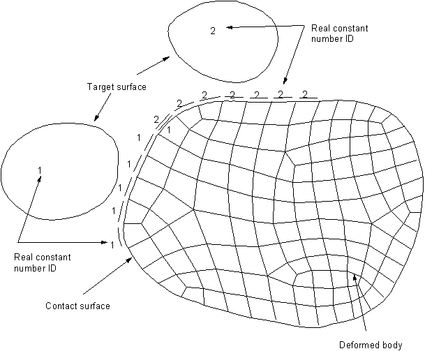
You must identify where contact might occur during the deformation of your model. Once you've identified potential contact surfaces, you define them via target and contact elements, which will then track the kinematics of the deformation process. Target and contact elements that make up a contact pair are associated with each other via a shared real constant set.
The contact zone can be arbitrary. However, for the most efficient solution (primarily in CPU time), you may want to define smaller, localized contacting zones. Be sure the zones are adequate to capture all necessary contact. Different contact pairs must be defined by a different real constant set, even if the element real constant values do not change. There is no limit on the number of surfaces allowed.
Depending on the geometry of the model (and the potential deformation), multiple target surfaces could interact with the same zone of the contact surface. In such cases, you must define multiple contact pairs (using multiple overlapping contact elements), each with its own real constant number. See Figure 3.1: Localized Contact Zones.
The geometry-based contact pair generation tools (see the Contact Wizard) may create unnecessary contact and target elements which are never in contact during solution. For modeling small-sliding contact or assembly contact, you can issue CNCHECK,TRIM to remove contact and target elements which are initially in far-field (that is, open and not near contact). The trimming is based on the contact pinball size—the smaller the pinball radius, the greater the number of contact and target elements that will be deleted. The contact trimming option is useful in distributed-memory parallel runs to achieve better performance.


