


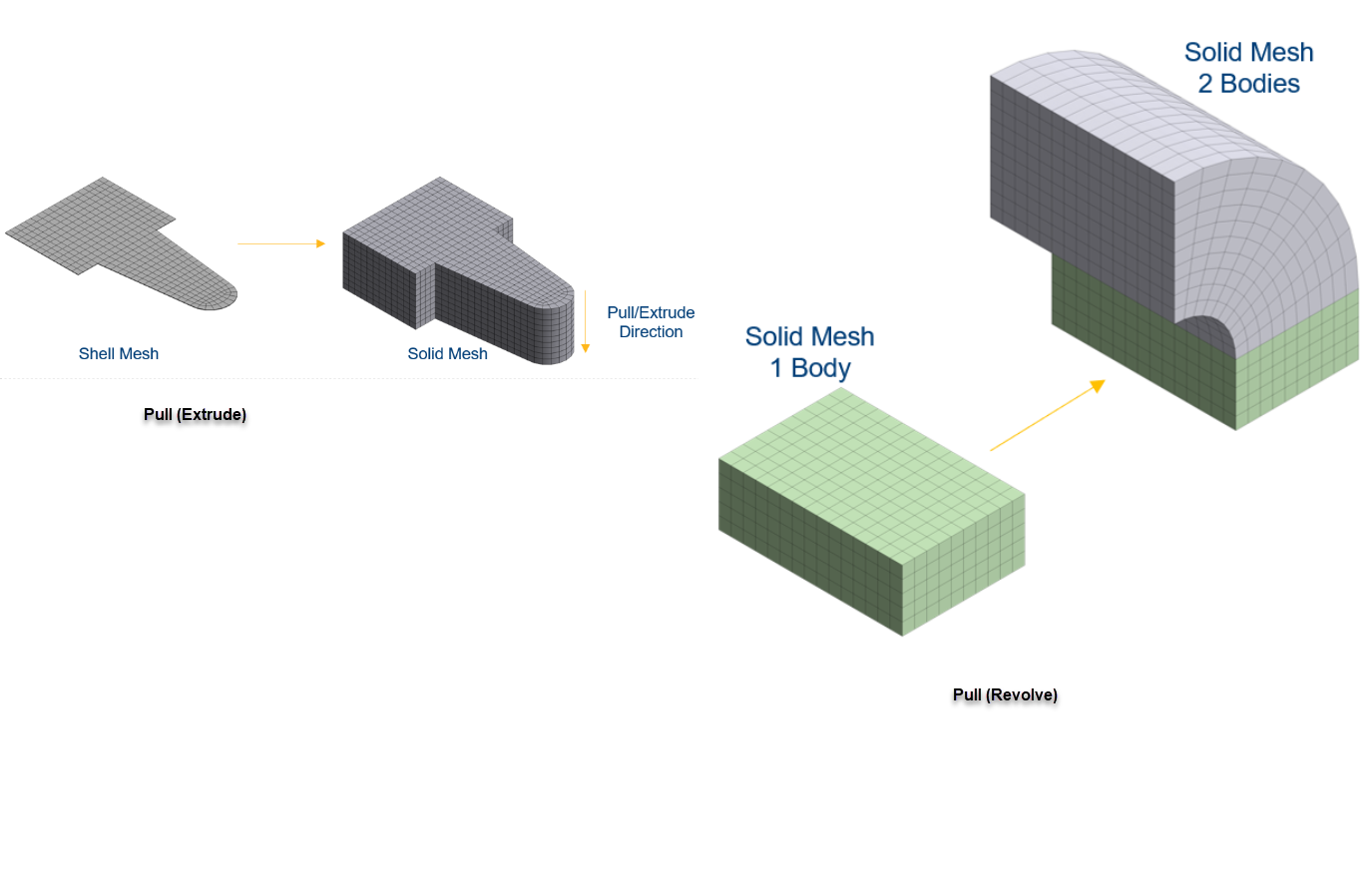
Pull enables you to extrude or revolve element faces, to generate solid mesh. Pull can be applied directly to scoped element faces,or geometric faces or bodies (only shell body) from a surface or solid mesh. Pull generates volume of solid elements for the specified height or revolved volume from the source mesh along the specified coordinated system or the face normal vector. Pull allows you to create surface coating on solid bodies, element faces and geometric faces belonging to the solid bodies to generate shell mesh.
Note: Pull cannot be accessed through Mesh only system.
Pull creates linear elements if the base mesh is having linear elements and quadratic elements if the base mesh is quadratic. Pull mesh supports curvilinear mid nodes for quadratic elements.
On the Tree view under Mesh object, right-click Pull > Generate Selected Pull to create Pull Part under the Geometry tree. The Pull part created is independent of the contents of the Pull mesh. When you Extrude or Revolve object from mesh data, the base mesh consists of solid element faces or surface elements. Each connected set of elements forms a body. Each body has a top, bottom and side face. Two edges are created bounding the top and bottom face. These edges are called ring edges and they do not have vertices.
When you Extrude or Revolve object from CAD topology, bodies of the Pull part match the bodies of the base mesh. Bottom faces of the pull bodies match those of base mesh and top face match the corresponding face of the base mesh. A side face is created for each edge of the CAD topology. Edges and vertices of Pull bodies are created to form watertight solids.
The exceptions to the above rule are the following:
When the mesh body having multiple parts are meshed using Batch Connections or Automatic (PrimeMesh) Method, a Pull part is created for a Pull feature.
When the Pull feature is Extrude up to target and the target is such that some of the base mesh must be removed to perform extrusion, you must apply the rules of extrusion of the mesh objects. Hence, the pull sides are not defined by the original CAD topology edges.
Note:
For Pull defined by CAD topology, if the Pull mesh is cleared or CAD model is refreshed, all loads and boundary conditions behavior follow the one defined by the CAD topology entities.
For Pull defined by mesh elements or element faces, if Pull mesh is cleared or CAD model is refreshed, all loads and boundary conditions need to be redefined.
Extrude scopes shell bodies, elements belonging to shell bodies, geometric faces of shell or solid bodies, element faces of solid bodies.
To access Extrude,
Right-click Mesh Object > Insert > Mesh Edit.
Right-click Mesh Edit > Insert > Pull > Extrude.
Click Pull (Extrude) on the Tree view and click Generate to perform extrude mesh.
The Details view displays the Pull (Extrude) options :
Scope
Scoping Method: Allows you to scope the model based on your selection. There are two options. They are Geometry Selection and Named Selection.
Geometry Selection: Allows you to scope elements, element faces, geometric faces and sheet bodies for Extrude.
Named Selection: Allows you to select the element facets and elements belonging to sheet and solid bodies for Extrude.
Definition
Method: Displays the selected method of Pull. This is a read-only field.
Extrude: Allows you to generate solid elements for specified number of layers and height
Height: Allows you to specify the total height for the volume of solid elements. Height allows only positive values.
Number of Layers: Allows you to specify the number of layers to be used for Extrude.
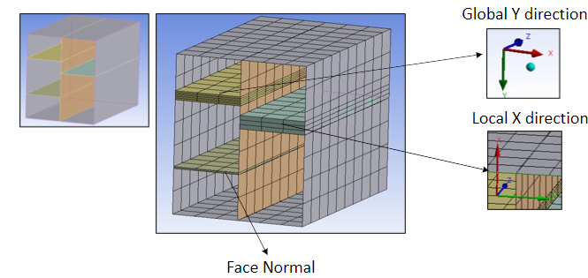
Extruded By: Allows you to specify the direction of extrusion. The available options are Use Coordinate System, Face Normal and Face Normal (Reversed).
Use Coordinate System: Allows you to generate elements in the specified coordinate system. When you select Use Coordinate System option in Extruded By, the Coordinate System and Use Coordinate System fields appear. The Coordinate System allows you to select the Global Coordinate System by default. The Use Coordinate System allows you to select any of the XYZ coordinate axis.
Face Normal: Allows you to generate elements along the face normal vector.
Face Normal Reversed: Allows you to generate elements along the opposite direction of the face normal vector.
Extrude Upto: Allows you to generate elements up to the specified target. The target can be faces from solids or sheet bodies and multiple faces with sharing geometric edge.
Element Option: Allows you to select the element type for the solver to use. The available options are Solid and Solid Shell. The default value is Solid.
Suppressed: Allows you to suppress the selected entities. You can select Yes to suppress the selected entities and No to unsuppress the selected entities. The default value is No.
Material: Allows you to select the material of your choice. You can also select a different material from the parent body material.
Revolve scopes shell bodies, elements belonging to shell bodies, geometric faces of shell or solid bodies, element faces of solid bodies.
To access Revolve,
Right-click Mesh Object > Insert > Mesh Edit.
Right-click Mesh Edit > Insert > Pull > Revolve.
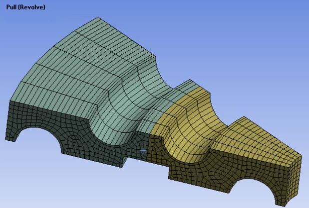
Click Pull (Revolve) on the Tree view and click Generate to generate pull elements along the revolution angle.
The Details view displays the Revolve options:
Scoping Method: Allows you to scope the model based on your selection. There are two options. They are Geometry Selection and Named Selection.
Geometry Selection: Allows you to scope elements, element faces, geometric faces and sheet bodies for Revolve.
Named Selection: Allows you to select the element facets and elements belonging to sheet and solid bodies for Revolve.
Definition
Method: Displays the selected method of Pull. Revolve allows you to generate solid elements for the specified number of layers and revolution angle along the edge coordinate system.
Revolution Angle: Allows you to specify angle of revolution for the solid elements. Here, Pull (Revolve) automatically merges the nodes of the first layer and last layer for 360 degrees revolution. Revolution Angle allows only positive values.
Number of Layers: Allows you to specify the number of layers to be used for Revolve.
Coordinate System: Allows you to select the Global Coordinate System by default. This option supports only Cartesian System.
Axis of Revolution: Allows you to select the coordinate axis along which the selected elements can be revolved. The available options are X Axis, Y Axis, Z Axis.
Suppressed: Allows you to suppress the selected entities. You can select Yes to suppress the selected entities and No to unsuppress the selected entities. The default value is No.
Material: Allows you to select the material of your choice. You can also select a different material from the parent body material.
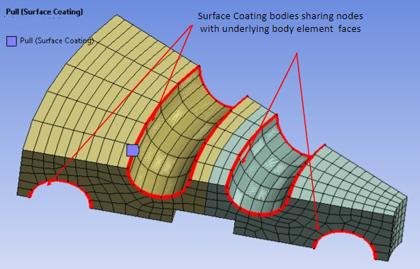
Surface Coating allows you to scope solid element faces. For mesh body, the bodies are created according to the bodies that own solid element faces. Each element face creates a topological face. Also, creates edges and vertices to form the topology. When you perform Pull on solid bodies with boundaries, bodies are created for each body that owns faces in the surface coating body and creates faces, edges, and vertices to match the topology of the base mesh.
To access Surface Coating,
Right-click Mesh Object > Insert > Mesh Edit.
Right-click Mesh Edit > Insert > Pull > Surface Coating.
Click Pull (Surface Coating) on the Tree view and click Generate to generate surface elements on the solid.
The Details view displays the Surface Coating options:
Scope
Scoping Method: Allows you to scope the model based on your selection. There are two options. They are Geometry Selection and Named Selection.
Geometry Selection: Allows you to scope element faces, geometric faces and solid bodies for Surface Coating.
Named Selection: Allows you to scope element faces, geometric faces and solid bodies for Surface Coating.
Definition
Method: Displays the selected method of Pull. Surface Coating allows you to create shell elements coating for the outer layer of the 3D objects. You can scope solid element faces, CAD faces and solid bodies through Geometry Selection and Named Selection.
Line Coating: Allows you to produce line elements coating the edges of the 2D axisymmetric objects only. When you scope an edge using Surface Coating, the Method automatically changes to Line Coating. When you generate Pull, line element are created under the Pull part in the Geometry tree. Pull (Surface Coating) supports multiple surface coating on the same body or face and on element faces.
Suppressed: Allows you to suppress the selected entities. You can select Yes to suppress the selected entities and No to remove suppression from the selected entities. The default value is No.
Material: Allows you to select the material of your choice. You can also select a different material from the parent body material.
Nonlinear Effects: Choose whether to include nonlinear effects. Options include (default) and .
Thermal Strain Effects: Choose whether to include thermal strain effects. Options include (default) and .
Stiffness Option: Allows you to provide the stiffness behavior of the shell body created by surface coating. The available options are Stress Evaluation Only, Membrane Only, Membrane and Bending.
Thickness: Allows you to specify the thickness for surface coating. The Thickness option is available only when the Stiffness Option is set to Membrane Only or Membrane and Bending.
Limitations
Pull cannot detect the intersection between the existing mesh and the created Pull or intersection between the two Pull objects. Pull can only detect self-intersection within a single Pull. Then, it provides an error message without creating Pull mesh.
If Pull is scoped to two element faces, geometric faces or disconnected bodies from disjoint bodies in the same model for performing Pull operation, two Pull bodies are created in the generated Pull part under Geometry on the Tree view.
When Pull is performed on a highly curved surface, the generated pulled elements may converge or intersect. Such elements are excluded from extrusion when Extrude Upto is set to Yes. When Extrude Upto is set to No, the Pull operation is aborted providing an error message.
When a solid object is added through Construction Geometry after generating the Pull object, you cannot generate mesh on the solid body. You must insert and mesh all solid objects before generating the first Pull object.
When you try to Pull (Extrude) using solid element faces, only single side face (perpendicular to extrude direction) is created instead of creating multiple faces as with the extruding topological entity.
When you select multiple Pull objects for performing Pull operations, you do not have the option to generate pull. However, to generate multiple Pull, you can select the Pull objects then right-click Mesh Edit > Generate.
When you suppress a Pull part under the Geometry tree, the Pull object under the Mesh Edit folder is not suppressed. It remains unchanged.
When you apply Pull on single bodies, Pull creates non conformal mesh. That is, nodes of the interfaces from parent body and pull body are not connected. You should define the manual contact to resolve the issue.
When you have a Pull object generated, the Node Merge option is not available when you try to insert it by right-clicking Mesh Edit > Insert > Node Merge. You can now select Beta Options from Tools > Options > Appearance to access the Node Merge in Pull.
Pull does not support cylindrical coordinate system.
Pull (Surface Coating) does not support rigid bodies.
Refresh is not supported when you scope mesh elements or element faces for Pull generation.
For geometries created using the Mesh Pull feature and exported as a Part Manager Database file, the Ansys Mechanical does not currently support re-meshing the part using normal mesh methods when you import the .pmdb file into a new Mechanical session.
When you perform Pull on a model having both solid and shell bodies, Pull scopes element faces of both solid and shell bodies without providing an error message.
When same elements are scoped through two different Name Selection, multiple Pull can be used to generate the Pull for the same elements without providing any warning message.
When you apply Pull on a model having multibody part with shared topology, it creates conformal mesh and shares topology between the bodies. Hence, if you do not want to share topology, you must transfer the model to Ansys Mechanical as multi-part assemblies.
For Extrude and Revolve, Pull automatically suppresses the base body and hides it in the graphics when:
Sheet body is scoped
All the geometric faces of a sheet or solid body is scoped
All elements of a sheet body are scoped.
When a single Pull is applied on the multipart assembly, the Pull creates non conformal mesh and may have self-intersection causing Pull failure. You may define separate Pull for each part of the multipart assembly for successful pull generation.
Line Coating does not support the interface between the 2D and 3D surfaces.
When you have meshed Pull (Surface Coating) objects on the Tree view and you insert a Pull (Extrude) or Pull (Revolve) object, the state change of Pull (Extrude) and Pull (Revolve) affect the state of Pull (Surface Coating).
Pull allows you to mesh only multibody parts with same order mesh. If mixed order mesh is scoped, then Pull generation gives error due to dropped nodes. To avoid this, Pull should have either linear or quadratic mesh as input and not both in a single Pull control.
When a generated Pull in a system is transferred to another system and both the systems are updated and then if you suppress the Pull in the first system and update both the systems, the updated Pull in the first system is not transferred to the Pull in the second system.
When Pull (Extrude, Revolve, Surface Coating) is duplicated, the scoping of the original Pull (Extrude, Revolve, Surface Coating) is not retained for the duplicated Pull (Surface Coating).
When there are multiple Pull (Surface coating) scoped to same body under the Mesh object on the Tree view,
Clearing mesh on the first Pull (Surface Coating), automatically clears the mesh on the second Pull (Surface Coating) and vice versa. Also, when this happens the Pull (Surface Coating) Part under the Geometry on the Tree view is not cleared for the second Pull.
Suppressing the second Pull (Surface Coating), affects the state of first Pull (Surface Coating) and vice versa.
Generating a second Pull (Surface Coating), clears and regenerates the first Pull (Surface Coating).
When you scope multibody parts such as solid and shell bodies sharing the edge which have mixed order mesh in Pull, self-intersections may occur when the Pull is generated along the face normal or face normal reversed. Hence, same order mesh should be scoped for the Pull and extrude direction should be specified using the coordinate system.
When bodies scoped for Pull are suppressed, the Pull mesh goes out of state but the Pull part remains on the Geometry tree.