


A symmetry region refers to dimensionally reducing the model based on a mirror plane. Symmetry regions are supported for:
Structural and Thermal Symmetry
A symmetric structural boundary condition means that out-of-plane displacements and in-plane rotations are set to zero. The following figure illustrates a symmetric boundary condition. Structural symmetry is applicable to solid and surface bodies.
Note: Thermal symmetry conditions are naturally satisfied.
Structural and Thermal Anti-Symmetry
An anti-symmetric boundary condition means that the rotation normal to the anti-symmetric face is constrained. The following figure illustrates an anti-symmetric boundary condition. Structural anti-symmetry is applicable to solid and surface bodies.
Note:
The Anti-Symmetric option does not prevent motion normal to the symmetry face. This is appropriate if all loads on the structure are in-plane with the symmetry plane. If applied loads, or loads resulting from large deflection introduce force components normal to the face, an additional load constraint on the normal displacement may be required.
Thermal anti-symmetry conditions behave the same way as symmetry conditions.
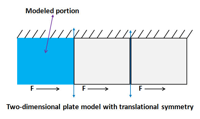
Structural and Thermal Linear Periodic Symmetry
The boundary condition is used to simulate models with translational symmetry, where the structure is assumed to repeat itself in one particular direction to infinity. This feature supports only a single direction for the entire model (more than one direction is not supported) for structural analyses and thermal/thermal-electric analyses. The application uses the Mechanical APDL command CE to apply this boundary condition in a structural environment as compared to the CP commands used in the thermal and thermal-electric environments.
For structural modeling with the Behavior property set to , the application creates a pilot node and specifies constraint equations for the high and low regions as follows:
| DOF(low) - DOF(high) = DOF(PilotNode) |
The Pilot Node is left unconstrained. The Pilot Node is sent to the Mechanical APDL solver using the following parameter (variable): _pilotNode
For structural modeling with the Behavior property set to , the application directly specifies constraint equations for the high and low regions as follows:
| DOF(low) - DOF(high) = 0 |
This forces DOF(low) to be coupled with DOF(high) in each pair of matched nodes.
Electromagnetic Symmetry
Symmetry conditions exist for electromagnetic current sources and permanent magnets when the sources on both sides of the symmetry plane are of the same magnitude and in the same direction as shown in the following example.
Electromagnetic symmetric conditions imply Flux Normal boundary conditions, which are naturally satisfied.
Electromagnetic Anti-Symmetry
Anti-Symmetry conditions exist for electromagnetic current sources and permanent magnets when the sources on both sides of the symmetry plane are of the same magnitude but in the opposite direction as shown in the following example.
Electromagnetic anti-symmetric conditions imply Flux Parallel boundary conditions, which you must apply to selected faces.