


Fan wheels, spur gears, and turbine blades are all examples of models that can benefit from cyclic symmetry.
An automated cyclic symmetry analysis conserves time and CPU resources and enables you to view analysis results on the entire structure for a Static Structural, Modal, or Full Harmonic Response analysis.
Note: Static and transient thermal analyses are also possible using the Cyclic Region object in Mechanical even though the cyclic symmetry solution in Mechanical APDL does not support elements with thermal DOFs. However, the results of analyses containing thermal DOFs can only be seen on a single sector.
When you use a Cyclic Region in an LS-DYNA analysis the results can only be seen on a single sector.
Ansys Workbench automates cyclic symmetry analysis by:
Solving for the behavior of a single symmetric sector (part of a circular component or assembly). See The Base Sector for more information.
Using the single-sector solution to construct the response behavior of the full circular component or assembly (as a postprocessing step). Not available in an LS-DYNA analysis.
For example, by analyzing a single 10° sector of a 36-blade turbine wheel assembly, you can obtain the complete 360° model solution via simple postprocessing calculations. Using twice the usual number of degrees of freedom (DOFs) in this case, the single sector represents a 1/36th part of the model.
Restrictions
Note the following when working with cyclic symmetry:
Always align Remote Force, Moment, and/or Nodal Force loading conditions with the same Z Axis direction used by the Cyclic Region object.
Note: Remote Force and Moment are not available in an LS-DYNA analysis. There is no limitation on the Nodal Force direction for LS-DYNA.
The presence of Mesh Connections in a body with cyclic symmetry definition may create conflicts within the mesh during the solution process.
Cyclic symmetry does not support the use of the Average Across Bodies option.
Note: For an LS-DYNA analysis, average results (results computed over an element, like stress and strain) can be displayed for a single sector. All display options (unaveraged, averaged, nodal difference, nodal fraction, etc.) are functional when displaying results for LS-DYNA analyses.
Layered Sections cannot be applied to a model that uses cyclic symmetry.
Mechanical 2D Analyses do not support cyclic results.
Line bodies are not supported for cyclic symmetry analyses.
Gasket bodies are not supported for cyclic symmetry analyses.
When specifying certain Probes (deformation, stress, strain) during Cyclic analyses, Mechanical does not currently support probes specified when the Location Method is set to:
.
and you define the associated Geometry property using the Hit Point Coordinate option (Graphics Toolbar).
Warning:
Make sure that you do not scope a Remote Displacement, Remote Force, or a Moment to a geometric entity that shares an edge, vertex, or node with either the specified High Boundary or Low Boundary properties of the Cyclic Region because the application could generate incorrect results.
Only Static Structural analyses support the ability to specify a Remote Point that coincides with the cyclic symmetry axis. In addition, for the analysis, you must:
Set the Remote Point Behavior property to or .
Set the Future Analysis option (Analysis Settings > Analysis Data Management) to None.
Make sure that you divide the load magnitude by the specified number of sectors.
A Remote Point scoped to a sector is equivalent to having one Remote Point for each sector in the expanded solution.
If you specify a node-based load, such as Direct FE loads, Remote Force, Moment, etc., on both the low and high edge nodes, it will be taken into account twice in the solution due to the cyclic constraint equations.
See the Modeling and Loading Limitations section in the Mechanical APDL Cyclic Symmetry Analysis Guide for more information.
General Application
The overall procedure in Ansys Workbench for simulating models that are cyclically symmetric is to run a static structural, modal, full harmonic, LS-DYNA, or thermal analysis and perform the following specialized steps:
Insert a Cyclic Region or Pre-Meshed Cyclic Region object. This step is necessary to enable Mechanical to perform a cyclic symmetry analysis. Multiple Cyclic Region objects are permitted but they must refer to the same Coordinate System to specify the symmetry axis and sweep the same angle. Only one Pre-Meshed Cyclic Region can be added and it cannot be used in combination with any other symmetry objects.
Note: Multistage Cyclic Symmetry Analysis is an exception. Each stage in a multistage cyclic symmetry analysis can have a different sweep angle and Pre-Meshed Cyclic Region.
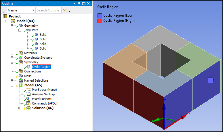
Define the low and high boundaries by selecting the appropriate faces in the Low Boundary and High Boundary fields. Each selection can consist of one or more faces over one or more parts, but they must be paired properly. To be valid, each face in Low Boundary must be accompanied by its twin in High Boundary. Also, ensure that each face and its twin belong to the same multibody part (although it is not necessary that they belong to the same body), using DesignModeler to adjust your multibody parts as needed.
Note:For the Periodic Region and the Cyclic Region objects, your low/high selections are used to match the mesh of the two boundaries.
The Pre-Meshed Cyclic Region object does not influence the mesh.
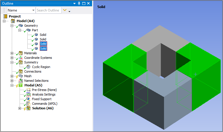
The example shown below illustrates two equally valid Low Boundary and High Boundary twin faces. One twin set of faces, located in the corner body, includes faces that are both included in that same body. Another twin set includes faces that are not on the same body, but are included in the same multibody part, as shown in the second figure.
Note: High Boundary and Low Boundary should be exactly same in shape and size, otherwise Mechanical will not be able to map nodes from Low Boundary to High Boundary to create full model from a single sector.
Continue with the remainder of the analysis. Consult the sections below as applicable to the analysis type.
Refer to the following sections for further details on cyclic symmetry:
- 15.1.3.1. Pre-Meshed Cyclic Symmetry
- 15.1.3.2. Multistage Cyclic Symmetry Analysis
- 15.1.3.3. Cyclic Symmetry in a Static Structural or Static Acoustics Analysis
- 15.1.3.4. Cyclic Symmetry in a Harmonic Response or FSI Harmonic Acoustics Analysis
- 15.1.3.5. Cyclic Symmetry in a Modal or FSI Modal Acoustics Analysis
- 15.1.3.6. Cyclic Symmetry in a Thermal Analysis