


Inflation is useful for CFD boundary layer resolution, electromagnetic air gap resolution or resolving high stress concentrations for structures.
The following sections provide the high-level steps to follow to assign inflation depending on the selected mesh method.
For information on setting global inflation controls and descriptions of all of the individual inflation controls, refer to Inflation Group. Alternatively, you can use local inflation mesh controls to apply inflation to specific boundaries. For details, refer to Inflation Control. For general information on applying inflation controls in combination with the various mesh method controls, refer to Meshing: Mesh Control Interaction Tables.
Inflation Controls With Sweeper
Inflation is a pre process for the sweeper. The source face is meshed and then inflated before sweeping with the sweeper.
Note:
Inflation is supported only on the source face(s) of the sweep (that is, inflation on the side faces). Inflation away from the source face(s) is not supported.
You do not have to select a source face for sweeping with inflation. You can simply pick faces for inflation and the Meshing application will internally place a Sweep method on the adjacent bodies using the inflated faces as the sources (unless another method already exists).
To add boundary layers to a source face for sweeping:
Apply a Method control to a body.
Set Method to Sweep.
Set Src/Trg Selection to Manual Source or to Manual Source and Target.
Scope the source (and target if Manual Source and Target was selected).
Set Free Face Mesh Type to , , or . Your selection determines the shape of the elements used to fill the swept body (pure hex, pure wedge, or a combination of hex/wedge respectively). The boundary region of the source/target faces will always be meshed with quad layers. Refer to Figure 184: Sweep Method With Inflation: Hex Fill and Figure 185: Sweep Method With Inflation: Wedge Fill.
Enter additional sweep settings, as desired, in the Details View.
Select the source face and insert an Inflation control.
Select the outer boundary edges of the source face for inflation (the edges that you want inflation to grow away from).
Enter additional inflation settings, as desired, in the Details View.
Mesh the body.
Note: If the target face has a different number of edges than the source face, the bias of the boundary layer may not be transferred correctly.
To obtain the mesh shown in Figure 184: Sweep Method With Inflation: Hex Fill, Free Face Mesh Type was set to . Notice the boundary region is meshed with quad layers.
To obtain the mesh shown in Figure 185: Sweep Method With Inflation: Wedge Fill, Free Face Mesh Type was set to . Notice the boundary region is meshed with quad layers.

Inflation Controls With Patch Conforming Mesher
Inflation can be either a pre process or a post process for the patch conforming mesher.
To add boundary layers to a face using the Patch Conforming Mesher:
Apply a Method control to a body.
Set Method to Tetrahedrons.
Set the tetrahedrons Algorithm to Patch Conforming.
Select the body and insert an Inflation control.
Select the faces to be inflated (the faces that you want the inflation layers to grow away from).
Enter additional settings, as desired, in the Details View.
Mesh the body.
Inflation Controls With Patch Independent Mesher
Inflation is a post process for the patch independent mesher after it has created the tetrahedron elements.
To add boundary layers to a face using the Patch Independent Mesher:
Apply a Method control to a body.
Set Method to Tetrahedrons.
Set the tetrahedrons Algorithm to Patch Independent.
Set the Min Size Limit.
Select the body and insert an Inflation control.
Select the faces to be inflated (the faces that you want the inflation layers to grow away from).
Enter additional settings, as desired, in the Details View.
Mesh the body.
Inflation Controls With MultiZone
To add boundary layers to a face using the MultiZone Mesher:
Apply a Method control to a body.
Set Method to MultiZone.
Select the body and insert an Inflation control.
Select the faces to be inflated (the faces that you want the inflation layers to grow away from).
Enter additional settings, as desired, in the Details View.
Mesh the body.
For more information, see MultiZone Support for Inflation.
Inflation Controls With MultiZone Quad/Tri Mesher
To add boundary layers to a face using the MultiZone Quad/Tri Mesher:
Apply a Method control to a body.
Set Method to MultiZone Quad/Tri.
Select a body or face and insert an Inflation control.
Select the edges to be inflated (the edges that you want inflation to grow away from).
Enter additional settings, as desired, in the Details View.
Mesh the body.
Note: Base mesh caching is not supported for MultiZone Quad/Tri, so a change to inflation controls requires remeshing.
Inflation Controls With Quadrilateral Dominant or All Triangles Mesher
Inflation is a pre process for the quadrilateral dominant mesher or all triangles mesher.
To add boundary layers to a face using the Quadrilateral Dominant or All Triangles Mesher:
Apply a Method control to a body.
Set Method to Quadrilateral Dominant or Triangles.
Select a body or face and insert an Inflation control.
Select the edges to be inflated (the edges that you want inflation to grow away from).
Enter additional settings, as desired, in the Details View.
Mesh the body.
Inflation Controls With Cartesian Mesher
Inflation is a Pre process only for the Body Fitted Cartesian mesher. For CFD physics only, three layers are created with total thickness proportional to Element Size; for other physics preferences, only only layer is created.
To add boundary layers to a body using the Cartesian Mesher:
Apply a Method control to a body.
Set Method to Cartesian.
Select the Method and add an Inflation control.
Enter additional settings, as desired, in the Details View.
Mesh the body.
Inflation Handling Between Bodies With Different Methods
The inflation handling between bodies where one body is meshed with the sweep method and one body is meshed with the patch conforming tetrahedral method requires some special consideration to ensure inflation layers propagate through the common interface. There are two such cases to consider:
The case in which the common interface of two bodies is also a source/target face of the swept body
The case in which the common interface of two bodies is also a side face of the swept body
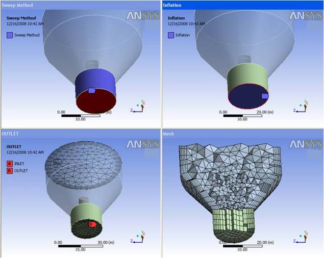
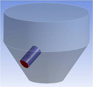
The model below will be used to explain the first case, in which the common interface of two bodies is also a source/target face of the swept body.
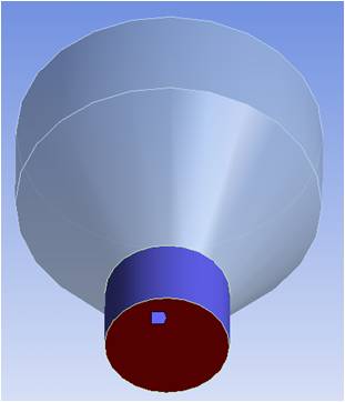
In this case, inflation on the patch conforming tetrahedral method must be defined off the faces of the wall (not common interface), or by using Program Controlled inflation (which ignores faces in Named Selections and common interfaces between bodies). The swept body needs the source face to be selected, and 2D inflation must be defined on the source face. Since 2D inflation does not support the Smooth Transition option, it is best to use another option so that the inflation between bodies will properly align.
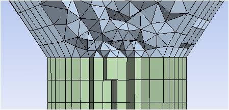
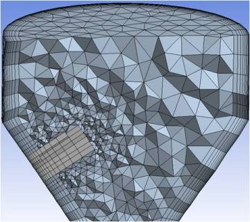
After properly setting up the model and ensuring the inflation of the tet body and the swept body have similar near-wall spacings, a mesh can be generated where the inflation layers will pass from one body to the next with proper connections on the common interface, as shown below.
The model below will be used to explain the second case, in which the common interface of two bodies is also a side face of the swept body.
In this case, inflation on the patch conforming tetrahedral method must be defined off the faces of the wall (not common interface), or by using Program Controlled inflation (which ignores faces in Named Selections and common interfaces between bodies). To properly align the inflated tet mesh to the side faces of the swept body, a biasing must be used along the sweep direction. Since the biasing along the sweep direction uses a different formulation than the inflation biasing, the following notes may be helpful.
The sweep bias ratio is the ratio of largest edge to smallest edge along sweep path, the growth ratio for inflation is a factor of the growth from the first element to the second element, etc. These relate as described below. The equation to get the inflation growth rate to align to the swept body is:
Ir = Sb (1/N-1)
where
Sb = Sweep Bias
N = Number of Divisions along sweep
Ir = Inflation Growth Rate
Also, to get proper alignment between the first layer of inflation and sweep, you need to use the first layer height of the swept mesh as first layer height for sweep.
Because the first layer height is computed by the software from the length of the sweep path, the sweep bias, and the number of divisions along the sweep—and there is no easy way to get the length of the sweep path—you should mesh the swept body first, measure the first layer height, and use this value as input for the First Layer Height option when defining inflation controls. The inflation growth rate can then be calculated using the formula above. This leads to well-aligned layers between the sweep and tet regions, as shown below.
Inflation and Baffles
The Meshing application provides support for meshing 0–thickness walls, or baffles, as non-manifold faces of a solid body. Inflation is supported. See Baffle Meshing for more information.