


The Patch Independent mesh algorithm for tetrahedrons is a "Top-Down" meshing algorithm based on the spatial subdivision algorithm which ensures refinement of the mesh where necessary, but maintains larger elements where possible, allowing faster computation. The Patch Conforming (PC) Tetrahedrons Algorithm is recommended for tetrahedral meshing but in some cases the Patch Independent Method can be helpful. For example, when meshing STL geometries or when geometry is dirty with badly formed surfaces which would require significant geometry clean-up to fix and mesh with Patch Conforming Tetrahedrons. After the root tetrahedron that encloses the entire geometry is initialized, the Patch Independent mesher subdivides the root tetrahedron to meet all element size requirements (that is, the prescribed local mesh sizes).
At each subdivision step, the edge length of the tetrahedron (=size) is divided by 2. This means that the prescribed sizes should all differ by factors that are an integer power of 2. The size of the root tetra is set to the smallest given size multiplied by 2n. All other prescribed sizes are approximated by subdividing the root tetra. Refer to the series of figures below, which illustrate the process that is followed by the Patch Independent tetra mesher.
At this point, the Patch Independent tetra mesher balances the mesh so that elements sharing an edge or face do not differ in size by more than a factor of 2.
After this is done, the Patch Independent tetra mesher makes the mesh conformal. That is, it guarantees that each pair of adjacent elements shares an entire face. The mesh does not yet match the given geometry, so the mesher next rounds the nodes of the mesh to the prescribed points, prescribed curves, or model surfaces. The Patch Independent tetra mesher then "cuts away" all the mesh, which cannot be reached by a user-defined material point without intersection of a surface.
Finally, the mesh is smoothed by moving nodes, merging nodes, swapping edges and in some cases, deleting bad elements.
Note: The Patch Independent Tetrahedrons method is being deprecated and will be removed in future releases.
The Method Details view has the following options:
Scope
Scoping Method: Allows you to scope geometry or named selection. The default value is Geometry Selection. The available options are:
Geometry Selection: Allows you to scope the geometry for MultiZone method.
Named Selection: Allows you to scope the available named selection for MultiZone method.
Definition
Suppressed: Allows you to suppress the selected control. The default value is No. When Suppressed is set to Yes, Active displays the status of the selected control. Active field is read-only.
Method : Allows you to select the meshing method.
Algorithm: Allows you to select the algorithm for meshing.
Element Order: Defines the element order for meshing. Refer to Method Controls and Element Order Settings.
Defined By: Allows you to apply settings to define the mesh size. The available options are Max Element Size and Approx Number of Elements per Part.
Max Element Size: Specifies the size of the initial element subdivision. The default value depends on the sizing options selected:
When Use Adaptive Sizing is set to No, the default value of Max Element Size is inherited from the global Max Size value.
When Use Adaptive Sizing is set to Yes, the default value of Max Element Size is inherited from the global Element Size value.
In either case, you can change the value if you want to apply a specific value locally. In such cases, the maximum size comes from the larger value of the global controls (that is, Max Size or Element Size, as described above) or, the largest scoped body size or face size that Patch Independent is also scoped to. A scoped edge size is not respected if it is larger than either the global size or the size on an attached face.
With the Patch Independent mesh method, scoped body sizing is supported as follows:
If the local body size defined is smaller than the global maximum size, the scoped body size is assigned inside the volume.
If the global maximum size is smaller than any scoped body, face or edge sizing, the global maximum size (Element Size when Use Adaptive Sizing is set to Yes, Max Size when Use Adaptive Sizing is set to No) is changed to be the same as the largest sizing within the mesher. For example, if Patch Independent is defined on two bodies, and the setup is as follows:
Global Max Size = 4
Local body size scoped to Body1 = 8
No local body size is scoped to Body2
The Patch Independent maximum size will be 8 and the global Max Size of 4 will be used for the sizing of Body2. You can paramterize Max Element Size.
Note: The maximum element size inside the volume of Body2 could grow to 8. Because setting local sizings affects the largest element size in the model, you should avoid setting local sizes that are larger than the global maximum size.
Approx Number of Elements per Part: Prescribes an approximate number of elements for the mesh. The default is 5.0e+005. Specifying a prescribed number of elements for the Patch Independent method is applicable only if the method is being applied to a single part. You can parameterize Approx Number of Elements per Part.
Feature Angle: Specifies the minimum angle at which geometry features are captured. If the angle between two faces is less than the specified Feature Angle, the edge between the faces are ignored, and the nodes are placed without respect to that edge. If the angle between two faces is greater than the Feature Angle, the edge should be retained and mesh aligned and associated with it (note the edge could be ignored due to defeaturing, and so on). You can specify a value from 0 (capture most edges) to 90 (ignore most edges) degrees or accept the default of 30 degrees. You can parameterize the Feature Angle.
Mesh Based Defeaturing: Ignores edges based on size. The default value is Off. When Mesh Based Defeaturing set to On, Defeature Size option is available.
Defeature Size: Allows you to enter a numerical value greater than 0.0. By default, the value of this local Defeature Size option is the same as the global Defeature Size. When you specify a different value for the Defeature Size, it overrides the global value. Specifying a value of 0.0, resets the tolerance to its default. If multiple Patch Independent tetra mesh method controls are defined with different tolerances, the smallest tolerance is respected. You can parametrize the Defeature Size.
Some basic cases include the following:
A small hole with a diameter smaller than the tolerance as shown below.
No edges are dropped. You should defeature manually in this case.
Two approximately parallel spaced edges (fillet or chamfer), as shown below.
To determine whether a face is a fillet or chamfer, the Patch Independent mesher evaluates the face's geometric features. To be considered as a fillet or chamfer:
A face must be at least twice as long as it is width.
A fillet or chamfer has either three or four sides (that is, two long sides and one or two short sides), all with angles <= 135 degrees.
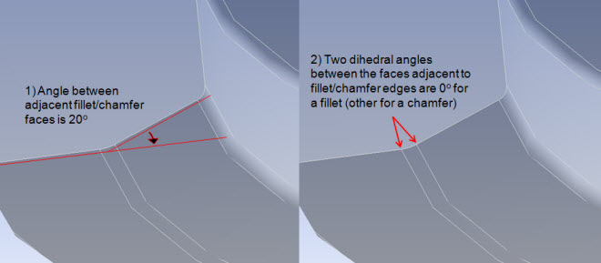
In the case of a fillet, which is a curved or rounded face, the angle between the fillet and a face attached to one of its long sides is 0 degrees (not 180 degrees). In contrast, a chamfer is a planar face and the angle between the chamfer and a face attached to one of its long sides is larger than 0 degrees.
For defeaturing of fillets or chamfers, the mesher considers the fillet or chamfer face as well as the faces adjacent to it (the faces attached to its long sides). The dihedral angles between these faces are evaluated to determine whether the attached edges of adjacent faces are respected (that is, whether nodes are placed with respect to the edges at the long sides of the fillet or chamfer).
There are three dihedral angles occurring at a fillet or chamfer:
One dihedral angle occurs between the two faces "touching," or adjacent to, the fillet or chamfer face. When this angle is compared with the Feature Angle, the angle is measured between the face normals at the imaginary edge where the two faces (virtually) meet.
Two dihedral angles occur between the fillet or chamfer face and the respective faces "touching," or adjacent to, the two long sides of the fillet orchamfer. The angles are evaluated as the angles between the face normals at the common edge of the fillet or chamfer and the attached face.
Defeaturing occurs as follows:
If the angle between the two faces adjacent to the fillet or chamfer face is greater than the Feature Angle, and the angles between the fillet or chamfer face and the faces attached to its long sides are less than the Feature Angle, and the minimum fillet or chamfer width is greater than the Defeature Size, both long sides or edges are respected.
If the angle between the two faces adjacent to the fillet or chamfer face is greater than the Feature Angle, and the angles between the fillet or chamfer face and the faces attached to its long sides are less than the Feature Angle, and the minimum fillet or chamfer width is less than the Defeature Size, only one long side or edge is respected.
If only one angle between the fillet or chamfer face and the faces attached to its long sides is greater than the Feature Angle, only one long side or edge is respected.
If none of the angles are greater than the Feature Angle, none of the long sides or edges are respected.
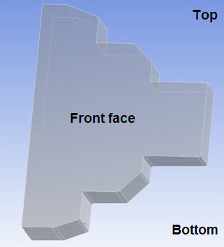
The following series of figures illustrates fillet or chamfer detection. In this example, a cross-section is revolved. The top and bottom of the section are identical, except the bottom has fillets or chamfers at each corner and the top does not. Because the definition of a fillet or chamfer is somewhat general, two cases are presented, each with a different angle of revolution. The angle of revolution is 5 degrees in the first case, as shown below. In this case, only the small faces fit the criteria of fillets or chamfers.
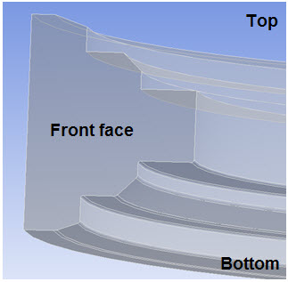
In the second case, the angle of revolution is 180 degrees, as shown below. In this case, all faces fit the criteria of fillets or chamfers, except for the front or back faces of the extrusion.
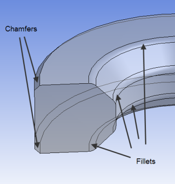
The figure below shows the angles that are considered for fillet or chamfer detection, and the small faces that are found to be fillets or chamfers.
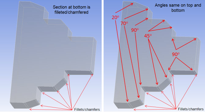
As described earlier, the angles that are considered for a given fillet or chamfer are:
the angle between adjacent fillet or chamfer faces.
the two angles attached to the fillet orchamfer.
Notice the angles in the figure below.
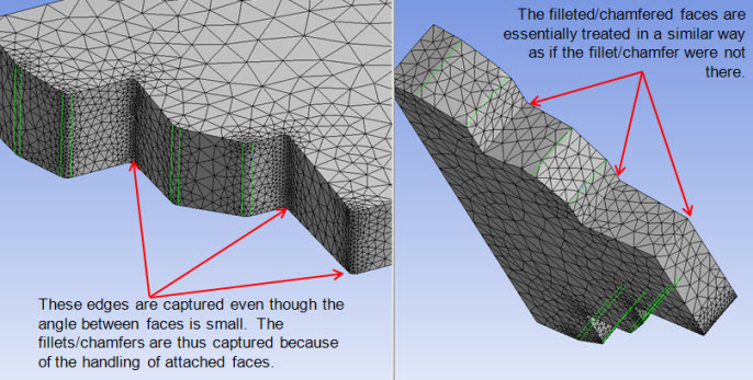
Notice the settings shown below, with Feature Angle set to 30 and Mesh Based Defeaturing turned off.
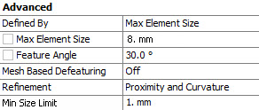
In the figure below, the highlighted edges are the edges that are ignored with the settings shown above. All edges are captured except for locations where the angle between faces or adjacent fillet/chamfer faces (two bottom edges) is 20 degrees. Changing the Feature Angle to a value below 20 results in the mesher capturing those edges, while increasing the angle results in more edges being ignored.
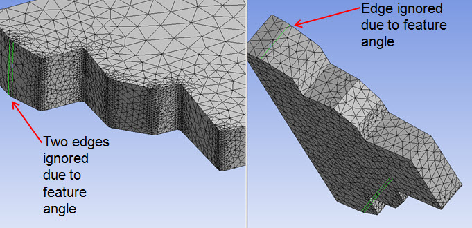
In the settings shown below, Feature Angle is changed to 80 but the other settings used before are retained.
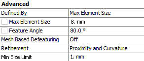
In the figure below, the highlighted edges are the edges that are ignored with the settings shown above. All edges are ignored except for those at angles of 90 degrees, both with or without fillets or chamfers.
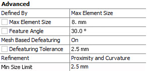
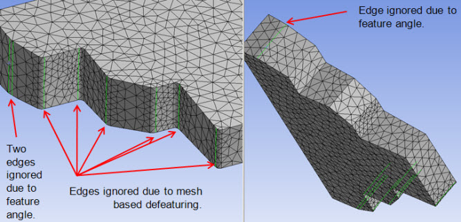
Now, consider the settings shown below. Here the Feature Angle is set back to 30, but Mesh Based Defeaturing is turned on. Both the Defeature Size and the Min Size Limit are set to 2.5 mm, which is larger than the bottom fillets or chamfers.
In the figure below, the highlighted edges are the edges that are ignored with the settings shown above. The same edges as before are ignored due to the feature angle, but in addition every other edge along the bottom fillets or chamfers is ignored.
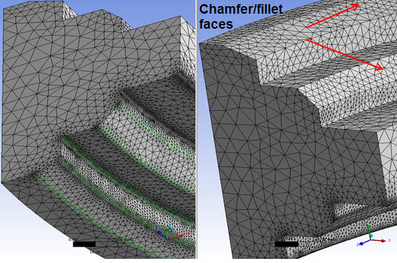
The last part of this example involves the case in which the angle of revolution is 180 degrees. Once again the Feature Angle is set to 80 but Mesh Based Defeaturing is turned off.
In the figure below, the highlighted edges are the edges that are ignored. With the settings shown above and the longer extrusion, more faces are found to be fillets or chamfers when compared to the case of the shorter extrusion. In comparison, the bottom section is identical as all faces are found to be fillets or chamfers (so the meshing behavior does not change). However, with the inclusion of all faces on top being considered chamfers, the meshing behavior does change.
The following series of figures shows examples of the Patch Independent Tetrahedron mesher with various settings. Figure (a) shows the base geometry.
Figures (b) through (f) below show examples of the Patch Independent Tetrahedron mesher under the conditions noted.
Refinement: Refines mesh automatically based on geometry curvature or proximity or both. This will result in larger elements on flat planar faces and smaller elements in areas of high curvature or within small gaps. The available options are No, Proximity and Curvature, Curvature and Proximity. The default value is Proximity and Curvature. For Explicit physics preference, the default vale is No. When you select Proximity and Curvature, Curvature or Proximity, the Min Size Limit option is available.
Min Size Limit: Prevents curvature or proximity based refinement from generating elements that are too small.
Curvature or proximity based refinement subdivides the elements until this Min Size Limit is reached. However, projection to geometry and smoothing may push the size even smaller for some elements. The default value of Min Size Limit depends on whether Use Adaptive Sizing is set to Yes or No.
When Use Adaptive Sizing is set to No, the default value of Min Size Limit is inherited from the global Curvature Min Size or Proximity Min Size control based on the Refinement type set. The mesher also uses the Min Size values defined locally.
When Refinement is set to Proximity and Curvature (default), the maximum of the global Proximity Min Size and Curvature Min Size is used as the default Min Size Limit.
When Refinement is set to Proximity, the global Proximity Min Size is used as the default Min Size Limit.
When Refinement is set to Curvature, the global Curvature Min Size is used as the default Min Size Limit.
Note: The global Curvature Min Size or Proximity Min Size values are used to determine the default value for Min Size Limit based on the Refinement type set for the Patch Independent method control, irrespective of the global refinement type set (for example, even if Capture Curvature and Capture Proximity are both set to No).
When Use Adaptive Sizing is set to Yes, you must specify a value for Min Size Limit.
Num Cells Across Gap: Specifies the number of cells desired in narrow gaps. This sets the goal for the proximity based refinement. The mesh will subdivide in tight regions toward this goal, but the refinement is limited by the Min Size Limit. It will not override this limit. Num Cells Across Gap is only available when Refinement is Proximity and Curvature or Proximity. The default value depends on the Sizing Options:
WhenUse Adaptive Sizing is set to No, the default value of Num Cells Across Gap is inherited from the global Num Cells Across Gap value.
When Use Adaptive Sizing is set to Yes, the default value of Num Cells Across Gap is 3.
In either case, you can change the value if you want to apply a specific value locally.
Curvature Normal Angle: Sets the goal for the curvature based refinement. The mesh will subdivide in curved regions until the individual elements span this angle. This refinement is also limited by the Min Size Limit. You can specify a value from 0 to 180. Curvature Normal Angle is available only when Refinement is set to Proximity and Curvature or Curvature.The default value depends on the Sizing Options:
When Use Adaptive Sizing is No, the default value of Curvature Normal Angle is inherited from the global Curvature Normal Angle value.
When Use Adaptive Sizing is Yes, the default value of Curvature Normal Angle will be computed based on the value of the Span Angle Center global option.
In either case, you can change the value to define specific values locally, but be aware that with Patch Independent Tet, only one value for curvature normal angle (num cells in gap) is used by the mesher. The smallest curvature normal angle (largest num cells in gap) is applied globally. A warning message will indicate this for you.
Figure 92: Example (c) Patch Independent Tetrahedron Mesher with Min Size Limit Set to Capture Curvature

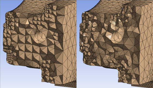
Smooth Transition: Determines whether the Octree volume mesh generated from the Patch Independent mesh method should be kept or whether it should be replaced with a Delaunay volume mesh starting from the Patch Independent surface mesh. The available options are On and Off. The default is Off. When Smooth Transition is set to On, the volume mesh is a Delaunay mesh. When Smooth Transition is set to Off, the volume mesh is an Octree mesh.
Figure 93: Effect of Smooth Transition Setting illustrates the effect of setting Smooth Transition to Off (Octree volume mesh on the left) or On (Delaunay volume mesh on the right).
Growth Rate: Represents the increase in element edge length with each succeeding layer of elements. For example, a growth rate of 1.2 results in a 20% increase in element edge length with each succeeding layer of elements. Specify a value from 1.0 to 5.0 or accept the Default. When set to Default, the value is the same as the global growth rate. When Use Adaptive Sizing is set to Yes, the Default is set differently based on Smooth Transition. When Smooth Transition is Off, the default is 2.0. When Smooth Transition is On, the default is 1.2.
Note: If Smooth Transition is Off, the growth rate is very approximate as the volume is filled with an Octree meshing approach which requires 2-to-1 transitions. Thus in such cases, the growth rate relates only to when the transitions occur through the mesh.
Minimum Edge Length: Read-only indication of the smallest edge length in the part.
Match Mesh Where Possible: The Match Mesh Where Possible control is applicable to contact definitions between faces. The available options are Yes and No. The default is Yes. If contact is defined by a single face that topologically belongs to two different bodies, setting this option to Yes has no effect. However, if there are independent faces on the two bodies, setting this option to Yes causes the Patch Independent mesh method to create nodes on both sides of the contact. The nodes are not connected but have identical coordinates.
Write ICEM CFD Files: Sets options for writing Ansys ICEM CFD files. Refer to Writing Ansys ICEM CFD Files for details.

Notes on Element Size Settings for the Patch Independent Tetra Mesher
Remember these notes when using the Patch Independent tetra mesher:
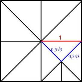
If you are specifying element sizes with the Patch Independent mesher, you may notice that some element edge lengths are less than the size that you have entered. For example, if your element size is 1, the resulting elements in a uniform tetrahedron mesh will have tetrahedron with edges of length 31/2/2 and edges of length 1. A single tetrahedron in this mesh will have two edges of length 1 and four edges of length 31/2/2. Two of the three dimensions of the bounding box of this tetrahedron will have length of 1 while the other dimension will have the length of 0.5. This correlates to an element size of 1.
If you are using Curvature and Proximity Refinement, you may notice that your elements are always less than the maximum size specified. Element growth rates with this mesher are always based on powers of 2. For instance, if your minimum size limit is set to 1 and your maximum element size limit is set to 5, and you have curvature in your model that warrants curvature based mesh refinement down to the minimum element size, you will see that the largest elements are not size 5 but size 4. This happens because in order to maintain elements at the minimum size limit, the initial tetrahedron must be some power of 2 larger than the minimum element size, which in this example case is 1.
Small features of Named Selections are checked in comparison to element size settings prior to meshing. If the minimum element size seems to be too big to capture the essential features of the geometry, a warning is provided if small entities could cause the mesher to fail.
Notes on Scoping for the Patch Independent Mesher
You can use the Patch Independent tetra mesh method in combination with other solid mesh methods in a multibody part, and the bodies are meshed with conformal mesh. Refer to Conformal and Non-Conformal Meshing for information about conformal meshing.
Notes on Virtual Topologies and the Patch Independent Mesher
Virtual topologies may affect the success of meshing with the Patch Independent tetra mesh method. Because virtual topologies are often a coarse approximation of the original faces or edges, the resulting small inaccuracies (gaps and overlaps) may cause the Patch Independent tetra mesher to miss some parts of the boundary of the virtual topology. As a result, the mesher may not accurately model the respected topology and may fail.
Since in general, the Patch Independent tetra mesh method does not require the use of virtual topologies to clean up the geometry, you can remove some of the problematic virtual topology and use Named Selections for boundary conditions instead, as appropriate.
Miscellaneous Notes for the Patch Independent Mesher
The Patch Independent tetra mesh method does not support mesh connections, contact matches, pinch controls, match controls, or face meshing controls.