Imported Load (Group)

Contains loads that you want to apply in the current analysis. You can import these loads from either an:

  • Upstream analysis system. The object is labeled Imported Loads (A6), where "A6" is an example upstream system identifier. The application automatically creates the Imported Loads object.

  • Mechanical APDL Result File. The object is labeled Imported Load (MAPDL Results File). For this object, you specify a file path to an existing result file (file.rst or file.rth).

  • Fluids Results File: The object is labeled Imported Load (Fluids Results File). For this object, specify a file path to an existing result file (Fluent or CFX result files, including .dat.h5, .dat.gz, and .res files).

  • External Data File: The object is labeled Imported Load (A2), where "A2" is an example upstream External Data system identifier or Imported Load (External Data).

In addition, the object provides context (right-click) menu options to add valid loads to the folder. The content of this section pertains to the Imported Load folder object as well as the imported/inserted load child objects.

Import Load (Upstream System/Result File) Object Properties

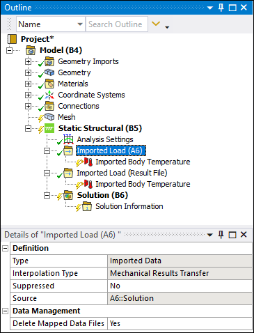
The Details view properties for the Imported Load folder object include the following.

CategoryProperties/Options/Descriptions

Definition

Type: Read-only indication.

Interpolation Type: Typically a read-only indicator of the application specified option for the property. Depending upon the analysis configuration and mapping, this property may provide selectable options.

Suppressed: Options include Yes and No (default).

Source: Displays the name of the Source system.

The following properties are available when you import load data from a Mechanical result file.

Source Dimension: Options include 2D (default for 2D analysis) and 3D (default for 3D analysis).
Result File: Use the field's option to open a dialog and browse to and select your file.
Result File Timestamp: Timestamp of when the result file was modified.
Result File Unit System: If the result file has a unit system, this property is read-only and displays the given unit system. If the result file does not have a unit system, this property enables you to specify a desired result file unit system.

Data Management

Delete Mapped Data Files: Deletes the files generated by the application during the mapping process. The default setting is Yes except for Imported Thicknesses. For Imported Thickness (Group) objects, you can set this option to No if you do not plan to run an Explicit Dynamics analysis.


Note:  This property does not display for Explicit Dynamics analyses because the files generated during the mapping process are required for the solution process.


Additive Manufacturing

Transfer Temperatures During Solve: Display when you insert an AM Process object. The property controls the transfer of temperatures from the Transient Thermal analysis during the solution process. Options include Yes (default) and No. See the LPBF Simulation Guide for more information.

Transfer Step: The step in the AM process during which the transfer of temperatures will occur. Options include Build Step (default) and Heat Treatment Step.

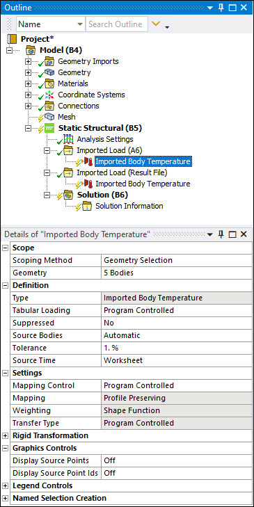
Imported Load Child Object Properties

The Details properties listed below are a comprehensive look at the child objects for the Imported Load folder. Based on the type of load you have imported, and the system from which it is imported, the display of the properties can vary.

CategoryProperties/Options/Descriptions

Scope

Scoping Method

Specify as Geometry Selection (default) or Named Selection. Supported scoping options vary per load type.

Geometry

Displayed when the Scoping Method is set to Geometry Selection (default). Displays the type of geometry or mesh entity and the number of entities to which the object has been applied using the selection tools. Use the selection filters to pick geometry or mesh, select the Geometry field, and then click Apply.

Named Selection

Displays when the Scoping Method is set to Named Selection. This field provides a drop-down list of available user-defined Named Selections.

Definition

Type

A read-only property that describes the object: [Imported Load Type].

Apply To

Displays for certain loads imported from External Data. It enables you to specify whether to apply the load to the centroid of an Elements (default) or to the Corner Nodes of each element.

Apply As

If you are importing a Temperature (Imported Temperature) load or a Thermal Condition (Imported Body Temperature) from an External Data system for a Coupled Field Transient, Steady-State Thermal, Transient Thermal, and Thermal-Electric analysis, this property becomes available. Using this property, you can apply the load as either a Boundary Condition (default) or an Initial Condition. The Initial Condition option applies the load from the External Data system as an initial condition on the scoped geometry or mesh.

Loaded Area

Becomes available when you import Pressure loads from an External Data system. Options include Deformed and Initial (default). The Initial option treats the scoped surface area as a constant throughout the analysis. Using the Deformed option, the application incorporates the change in the surface area as a result of deformation throughout the analysis. The selection for this property can be of significance during large deflection problems.

Tabular Loading

Options include Program Controlled (default), Ramped, Stepped, and Off.


Limitation:  When you set this property to either Program Controlled or Off, the application may display the data in the Graph as ramped. This may not represent how the application sends the load data to the solver.


Mapped Data

This property is only available when you have an Imported Velocity. Options include To Input File (default) and To Binary File.

Apply To Initial Mesh

Available for Imported Displacement, Imported Body Temperature, and Imported Pressure loads when a Nonlinear Adaptive Region is present. Options include Yes (default) and No. Using the Yes option applies the loading and constraint directly on the initial mesh for each load step for nonlinear adaptivity. Using the No option applies the loading on the current mesh. For more information, see the Initial-Mesh Loading and Constraint section in the Nonlinear Adaptivity Analysis Guide of the Mechanical APDL documentation.

Suppressed

Include or exclude the object in your analysis (Yes or No).

Source

Read-only property that displays the linked upstream system.

Source File

Options in Worksheet (default), All, and Range.

Overrides Constraints

Options include No (default) and Yes.

Source Bodies

Options include All (default), Manual, and Named Selection (Imported Velocity only).

  • When you set the property to Manual, the property Material IDs also displays. You may specify one or more source bodies using their Material ID value.

  • When you set the property to Named Selection, the Source Component property also displays. This property provides a drop-down menu that enables you to select a Named Selection defined in the upstream system.

Specify RPM

This property is only available when the Mapped Data property is set to To Binary File. As such, the Imported Velocity has a source file that is RPM-based. Options include:

  • Single (default): Applies the Imported Velocity on single RPM load step.

  • All: Applies the Imported Velocity on all RPM load steps.

  • By RPM Set: Selecting this option displays the RPM Set Numbers property displays. Use the RPM Set Numbers property to specify the desired RPM set or sets in the supported format (1, 2, 5-10). These values correspond to the number of Number of Steps property defined in the Step Controls category of the Analysis Settings object.

RPM Selection

This property provides a drop-down list of available RPM values included in the RPM-based source file. If you set the Mapped Data property to To Binary File, the values available from this property are based on the setting of the Specify RPM property.

Source Frequency

Specify the source frequencies used for mapping. Options include:

  • All (default): The application processes all frequency values in the solution.

  • Range: Specify a range of frequency values. Selecting this option displays a Minimum and Maximum property you use to define a minimum and a maximum value for the frequency range for the solution.

  • Worksheet: The application processes all of the frequency values of the Data View worksheet. You can change worksheet content as desired.

  • By Order (Imported Velocity only): This option displays the Order Numbers property. Use the Order Numbers property to enter one or more order numbers in the supported format (1, 2, 5-10). The application processes the source frequencies with respect to the order-based frequencies using the following calculation:

    Order Frequency = (Order x RPM)/60

Submodeling Type

Read-only indicating 3D to 3D or 2D to 3D.

Transfer Key

See the Submodeling section of the Special Analysis documentation, based on how you have your systems linked.

Source Time

See the Imported Boundary Conditions section of the Mechanical User's Guide.

For properties associated with data transfer, such as Mapping Controls, Rigid Transformation properties, Graphics and Legend Controls and Named Selection Creation, see the Data Transfer Mesh Mapping for details about the associated properties.

Tree Dependencies

  • Valid Parent Tree Object: Environment object.

  • Valid Child Tree Objects: Comment, Image, and valid load type objects.

Insertion Methods

  • If you are importing load data from an upstream system, the application automatically places the object beneath the analysis Environment object.

  • If you wish to import load data from a result file, insert the object using the Imported Load menu of the option on the Environment Context tab. You can also use the context (right-click) menu option available from the Environment object or from within the Geometry window to insert imported load data. Menu options include:

    • MAPDL Result File

    • Fluids Results File

    • External Data

Right-click Options

In addition to common right-click options, relevant right-click options for this object include:

  • Insert > [Imported Load Type based on analysis]

  • Create Velocities and Sync Analysis Settings: Use this option to automatically select DPF to generate a binary file to map imported data. This option is available when the linked upstream system, either Coupled Field Harmonic, Harmonic Acoustics, or Harmonic Response, is solved with the Multiple Steps property set to Yes and the Number of Steps property is set to a value greater than 1. When selected, the application automatically:

    • Creates one Imported Velocity child object.

    • Sets the Mapped Data property to To Binary File and the Specify RPM property to All.

    • Synchronizes the Analysis Settings object with the settings of the upstream system.

  • Import Load

  • Refresh Imported Load (Imported Load object only)

  • Suppress/Unsuppress

  • Clear Generated Data

  • Group Similar Objects

Child load objects include the above options as well as the option Export > Export Text File.

API Reference

See the Imported Load Group section of the ACT API Reference Guide for specific scripting information.

Additional Related Information

See the following sections for more information: