When using nonlinear adaptivity, you can apply loading and constraint directly on the initial mesh for each load step rather than on the new generated mesh only.
The ability to apply loads and constraints on the initial mesh is useful if you want to set up some loading for all load steps in advance but the loading information is available based on the initial mesh only. For example, in a multiple-load-step, one-directional, thermal-structural coupled analysis, the thermal analysis is based solely on the initial generated mesh, while the structure analysis with nonlinear adaptivity for each load step is dependent on the corresponding thermal temperature result of the initial mesh.
Supported loading types are:
Loads and constraints applied on the initial mesh are mapped and transferred to the current mesh for each specified load step.
Note: If you define loads on nodes that exist in both the current and initial meshes simultaneously for a given load step, the loads defined on the current mesh take precedence and loads applied on the initial mesh are ignored.
Initial-mesh loading and constraint supports limited large-deflection effects (NLGEOM, ON). If the deformations are very large, however, the current mesh may differ substantially from the initial mesh, leading to approximations (loss of accuracy) or load-transfer/mapping failure. For very large deformations, use this capability with caution.
Initial-mesh loading and constraint also supports geometry-preserving adaptive analysis (NLAD-GPAD). Because NLAD-GPAD is topology-dependent, however, the current mesh from remeshing may differ substantially from the initial mesh, leading to approximations (loss of accuracy) or load-transfer/-mapping failure. In such cases, use this capability with caution.
Due to the differences between initial and current mesh configurations, some approximations occur during mapping of loads/constraints between load steps (especially for curved geometry locations after multiple remeshings). The larger the difference, the greater the approximation. To improve the accuracy and consistency of mapping and load transfer, maintain the boundaries for the region with defined loads and constraints. After applying initial mesh-based loading and constraints, review the boundary conditions on the current mesh after remeshings at subsequent load steps to ensure that they are as desired.
Recommendation: Define appropriate element components to include the boundary nodes encompassing the
initial mesh-based displacement constraints or other loadings. Maintain the constraint
boundaries during remeshing (CM with KOPT)
for the defined element components. This practice is especially recommended for
gradually curving regions where remeshings could lead to boundary discontinuities
between the defined and undefined boundary condition regions.
Limitations:
Initial mesh-based loading and constraint is not valid for nonlinear mesh adaptivity for element-type change (NLAD-ETCHG).
SFCONTROL is not supported for these command options:
KTAPER= 2,KAREA= 1, orKFOLLOW= 1 with large-deformation effects (NLGEOM,ON).
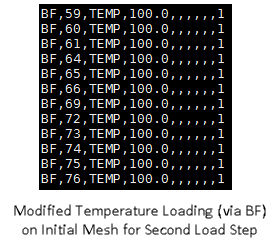
The following figures show how to define nodal temperature loading on the initial mesh, and the how the temperature loading transfers from the initial mesh to the current mesh:
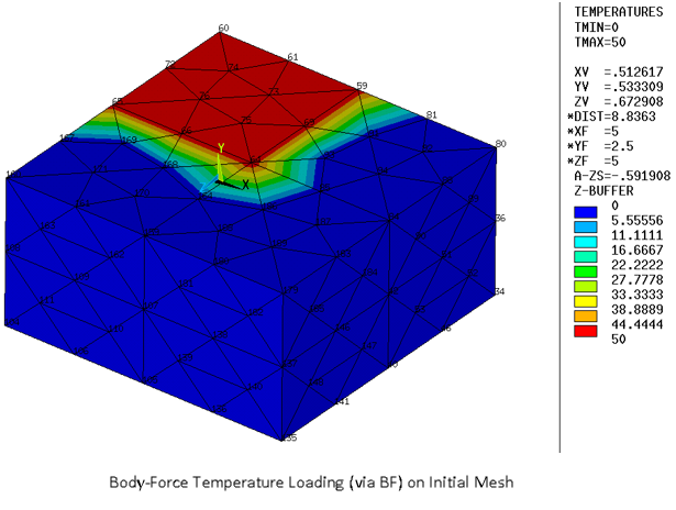
For the second load step, a specified nodal temperature load is applied on a quarter of the top surface (BF) to the nodes of the initial mesh. (Some nodes on the initial mesh were dropped during remeshing activity in the first load step.)
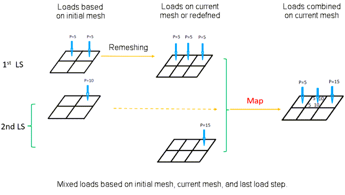
This figure shows how the mixed-pressure loading from the previous load step, the current load step on the initial mesh, and the current load step on the current mesh combine to form the current load-step pressure loading on the current mesh: