


The External Data system enables you to import data from text files into a Mechanical system or a System Coupling component system.
You can link an External Data system with the following Mechanical analysis types:
Coupled Field Static.
Coupled Field Transient. Supported loads include Imported Thermal Condition and Imported Temperature.
Explicit Dynamics. Note that, at this time, the Explicit Dynamics system and the LS-DYNA ACT extension provide only limited support for External Data Import.
Modal. Supported loads include Imported Body Temperature.
Static Structural and Transient Structural. These analysis types do not support the use of the Rigid Dynamics solver for External Data import.
Steady-State Thermal, Transient Thermal, and Thermal-Electric.
Note: There are certain limitations and/or requirements for some of the analysis types. See External Data Import in the Mechanical User's Guide for additional information about defining and processing your source data once you have imported it into Mechanical.
You must specify the data format in order to process the files in the External Data tab. This information can then be transferred to a downstream Mechanical system where the data can be applied as loads in an analysis.
Note: If the project has an External Data system that consumes files stored within the design point path and multiple design points, updating the multiple design points can cause the project to fail or produce inaccurate data. When a different design point is run, the External Data system does switch to the new design point's file path for the files it requires, and cannot be made to do so within an update of multiple design points.
For more details, see the following topics:
To import external data using an External Data system:
To add an External Data component system, drag the system from the Toolbox to the Project Schematic or double-click the system in the Toolbox.
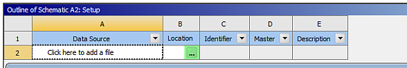
To open the External Data tab, double-click the Setup cell or right-click the Setup cell and select from the context menu.
In the Outline of Schematic pane, in the Location column, click
 .
.Browse to the location of the file to add.
Note: Importing files from design point folders within the same project directory (with the exception of the Current design point) is not supported.
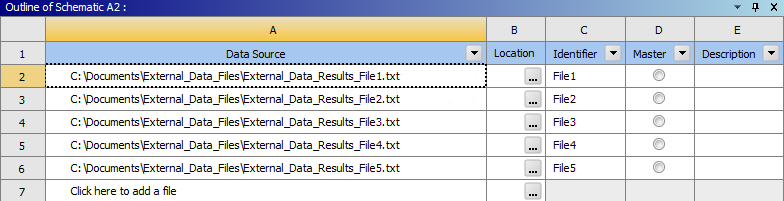
Select the file and click .
The selected file name, location, and identifier are automatically displayed in the Data Source column. The identifier is a string that can be used to identify the file in the downstream Mechanical application.
If required, click the cell in the Description column and type a description for the file.
Optionally, to duplicate an existing file, right-click the file in the Data Source column and select from the context menu.
To assign a main file, select the check box next to the required file.
Set a main file so that the system displays and uses the Properties for this file only. The nodal coordinate data for the selected main file is processed by the mapping utility. Any nodal coordinate data contained in non-main files is skipped.
You can select only one file to be the main file. If you multi-select a main file and non-main files, the Dimension, Length Unit and Transformation properties in the Definition pane are hidden. If you duplicate the main file, only one instance is designated as the main file.
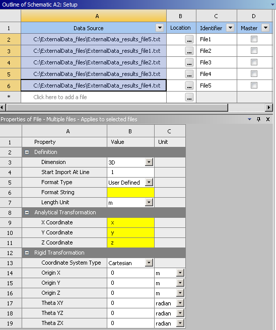
In the Properties of File pane, input the information required to process the file and apply the data in Mechanical.
If you select multiple files in the Data Source column, the Properties of File pane displays:
A value when that value is the same for all selected files
A blank field when values differ between selected files
A yellow field when a value is required, but not currently specified for at least one of the files
If you edit any field in the Properties of File pane when multiple files are selected, your change is applied to all files.
Note: Although you can multi-select files in the Data Source pane, when you click away from that pane the highlighting applied to those files disappears. However, the files remain selected and operations subsequently performed will be applied to all of the selected files.
Property Description Dimension Imports data from 2D or 3D models. If the 2D option is selected, you can import data only at the X and Y coordinates. The Z coordinate is not supported for the 2D option. Start Import at Line Sets the line number at which you want the data import to start. Line numbers start at 1. Format Type Sets the format specification used for the file. If you select Delimited, specify the character that delimits data elements in a line in the Delimiter Character field. The options are Comma, Semicolon, Space, Tab, or User-Defined. The latter choice enables you to specify any character as the data delimiter.
If you select User-Defined, specify the format using the following allowed format specifiers:
Decimal floating point: F or f
Scientific notation (exponent) using E/e character: E or e
Signed decimal integer: D or d
Signed integer: I or i
Character: A or a
Ignore flag: X or x
Dummy Net Data For External Data files that include trace mapping, selecting this option enables you to import trace data belonging to the dummy net of the file. Length Unit Specifies the unit system in which source point locations are defined. Coordinate System Type Specifies the nature of the source point locations. Options include Cartesian (X, Y, Z) or Cylindrical (R, theta, Z). The default value is Cartesian. Average Data at Midside Nodes If set to Yes, the data at Midside nodes, if not specified, is calculated as average of data specified at corner nodes. Note: This property is only available when Format Type is Delimited or User Defined and .cdb file is chosen as the main file.
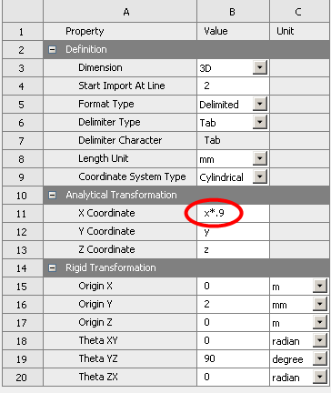
Material Field Data When selected, maps values from an external user-defined file to the nodes or elements of your mode. Once active, Field Variables become available in the Data Type drop-down menus in the Table of File pane. X/Y/Z Coordinate Enables you to apply scaling factors or functions to the corresponding column Data Type selected in the Table of File pane. For example, to scale all values for the X Coordinate column by 90%, change the X Coordinate text entry to x*0.9. When the Coordinate System Type is cylindrical, the X Coordinate will refer to the radius and the Y Coordinate refers to the angle. By default, each X, Y, and Z Coordinate is set to x, y, and z.
For a complete list of supported functions, see Working with Parameters. For an example, see Applying Source Point Analytical Transformations.
Note: When the Dimension type is 2D, the Z Coordinate is not shown.
Rotations, resulting from specified analytical transformations, do not get applied to mapped data (pressure, displacement, force) in a downstream Mechanical system.
In the example below, the line has one integer followed by four exponential data types.
385 8.333333333E-003 9.375000000E-003 3.375000000E-001 0.000000000E+000
In the example below, the line has one integer followed by four exponential data types.
385 8.333333333E-003 9.375000000E-003 3.375000000E-001 0.000000000E+000
The corresponding format is
1i3,4e17.9
Where:
The first entry is the number of occurrences
The second entry is the format specifier
The third entry is the number of characters of data in the definition (including numeric values (0-9), the letter 'e' (for instances of scientific notation), and any white space and + or - signs)
The fourth entry is the number of digits after the decimal point.
Tip: By default, Excel puts a minus sign at the beginning of a negative number but it does not put a plus sign at the beginning of a positive number, which changes the number of characters in the negative version of a number. However, if you select a column in Excel and apply a custom format, you can have a plus sign added to positive numbers. In Excel's Format Cells dialog box, set the Type with an example of the format for a positive number and a negative number, separating the two types with a semicolon. For example:
+00.00E+00;-00.00E+00
Based on the format details you specified in the Properties pane, you must define the data types and their corresponding units in the Table of File pane. The allowed Data Type values include:
Body Force Density
Displacement
Element ID
Element Orientations
Force
Heat Flux
Heat Rate
Heat Generation
Heat Transfer Coefficient
Node ID
Not Used
Pressure
Strain
Stress
Temperature
Thickness
Velocity
X Coordinate
Y Coordinate
Z Coordinate
Note:The Node ID field is useful when the nodal locations and values on nodes are specified in different files, as is the case when one of the files is specified as the main file. They are not meant to apply the values directly on the nodes of the target mesh. If a file is set up without specifying the nodal locations (X/Y/Z), all the points from the file default to (0,0,0). Similarly, the Element ID field is useful only when used in conjunction with a CDB file.
Thickness uses the
LengthData Unit and the Data Identifier should start withThickness.
Tip: You can multi-select rows (from the left-most column in the Table of File pane), then right-click to set all highlighted Data Type values or Data Unit values (where applicable) at the same time.
Column data is ignored if the Data Type is set to Not Used.
When Coordinate System Type is set to Cartesian in the Properties pane, the Data Unit cell for the X, Y, and Z Coordinates is read-only in the Table of File pane. When Coordinate System Type is set to Cylindrical, the Data Unit cell for the Y has a combo box that can specify its Data Unit string (either as Degrees or Radian).
You can change the data identifier from the default string for allowed data types. The data identifiers are appended to the file identifier, specified in the Properties pane, so that you can pick the correct source data in the downstream Mechanical application.
A preview of the file is shown in the Preview pane. The first ten imported lines are shown.
When you multi-select files, the Preview pane is disabled and the Table of File pane displays data in columns that you can sort and filter from the down arrow beside each column heading.
To delete files that you have selected (or multi-selected) right-click one of the files in the Outline of Schematic pane and select Delete from the context menu.
To modify any file in the Outline of Schematic pane, in the Location column, click
and select a new file. Switch to the Project tab.
Display the properties for the Setup cell of the External Data system by right-clicking on the cell and selecting . Specify the Files Import Type property as needed. Options include and (default). The option instructs the application to directly reference the External Data file instead of transferring the file to the project folder. For large size files, this action can drastically reduce disk storage requirements and improve performance.
Note: When you specify the option and wish to archive your project using the option of the Archive Options dialog, the application automatically copies the External Data files to the archived project.
Important: The option cannot be used with the System Coupling feature.
If required, link the Setup cell of the External Data to a Model cell or to a Setup cell of a Mechanical system (except for Rigid Dynamics Systems).
You can modify any file in the Outline pane by browsing to a new file using the browse option provided in the Location column
Note: If you modify an External Data system's data file outside of Workbench, you must re-read the data file. To do so:
Right-click the Setup cell
Select Re-read Input Files from the context menu.
The Re-read Input Files operation causes Workbench to regard the file as having changed, whether the file has changed or not, and the status of the Setup cell is updated appropriately.
To add a downstream Mechanical system, either drag a valid analysis system from the Toolbox and drop it on the appropriate Setup cell of the External Data system, or right-click the Setup cell and choose the Transfer Data To New context menu option.
For additional information for using the data in a downstream Mechanical application, refer to External Data.
You can import a circuit board’s trace layout file (ODB++
TGZ, Ansoft ANF,
BOOL + INFO, or Icepak COND +
INFO) into the Model cell of aMechanical
system.
To import a trace file:
To add an External Data component system, drag the system from the Toolbox to the Project Schematic or double-click the system in the Toolbox.
To open the External Data tab, double-click the Setup cell or right-click the Setup cell and select from the context menu.
In the Outline of Schematic pane, in the Location column, click
.Browse to the location of the trace file.
Select the file and click .
The External Data component enables you to perform rigid transformations to the trace file. When any required transformations are complete, drag the External Data Setup cell to a Mechanical system’s Model cell.
Note:
If you import a project from Release 16 that has an External Data system, you will not immediately be able to load in trace files. In order to import a trace file, you must delete the connection between the External Data Setup cell and the downstream Model cell, and then recreate the connection. The new connection will support the transfer of trace files.
For trace-file imports, the Table and Preview panes are disabled.
You can import a Mechanical APDL-generated CDB file as a source file.
To import a CDB file:
To add an External Data component system, drag the system from the Toolbox to the Project Schematic or double-click the system in the Toolbox.
To open the External Data tab, double-click the Setup cell or right-click the Setup cell and select from the context menu.
In the Outline of Schematic pane, in the Location column, click
.Browse to the location of the CDB file.
Select the file and click .
The Format Type property is automatically set to .cdb.
CDB files have certain restrictions:
The Start Import at Line setting is disabled as the entire file is read as data. Delimiter Type, Delimiter Character, and Format String are also disabled.
The data is always in the Cartesian global frame-of-reference.
The Table and Preview panes are disabled, so you cannot specify data types or preview data.
Mechanical APDL CDB files can be added as a parent mesh in the External Data system. The file must be generated using ‘blocked’ formatting (see CDWRITE in the Command Reference). Files generated in unblocked format are not supported. Only NBLOCK and EBLOCK data will be read from the file. Elements defined in the EBLOCK command should also have a corresponding element type and number (ET command) defined in the CDB file. No load/data transfer information is read.
The following element types are ignored during reading of the file:
Solid168
Targe169,170
Conta171,172,173,174,175,176,177,178
SURF152,153,154,156
Data transfer information must be defined in separate files, which also must be added to the same External Data system. These files must have a column providing node identifiers that match the node IDs defined in the Mechanical APDL CDB file. If the data transfer file contains element nodal values, then both node and element identifier columns need to be defined. Element values are not supported.
Note:
An element defined in the CDB file is ignored by the common mapping utility if any of the below conditions exist. The ignored elements are not used when data is mapped in the downstream application.
One or more of the nodes forming the element are not defined in the NBLOCK command.
The element does not have a corresponding element type and number (ET command) defined in the CDB file.
CDB files must contain only solid elements or shell elements, but not both.
For nodal data transfers, the number of nodes in the Mechanical APDL CDB file must match the number of data transfer items in all child files.
If data is not available at midside nodes, then the Average Data at Midside Nodes property can be used to specify the data at midside nodes as an average of data at corner nodes.
You can import an Ansys external data file (.axdt) as a source file.
To import an Ansys external data file:
To add an External Data component system, drag the system from the Toolbox to the Project Schematic or double-click the system in the Toolbox.
To open the External Data tab, double-click the Setup cell or right-click the Setup cell and select from the context menu.
In the Outline of Schematic pane, in the Location column, click
.Browse to the location of the Ansys external data file.
Select the file and click .
The Format Type property is automatically set to Ansys External Data File.
The Length Unit property is not available because this information is specified in the file. All length unit information in the .axdt file must be the same (all meters, for example).
The Start Import at Line setting is disabled as the entire file is read as data. Delimiter Type, Delimiter Character, and Format String are also disabled.
Ansys External Data File Format
CFD-Post and the Mechanical application can export external data files (.axdt) that can be used by the External Data system.
Note: The Mechanical application does not export temperature data in units of K.
The following is an example of an .axdt file that has been exported from CFD-Post:
[Name]
Plane 1

[Data]
X [m] (X coordinate), Y [m ] (Y coordinate), Z [ m ] (Z coordinate),
Wall Heat Transfer Coefficient [W m^-2 K^-1] (Heat Transfer Coefficient),
Wall Adjacent Temperature [K] (Temperature)
-1.77312009e-02, -5.38203605e-02, 6.00000024e-02, 7.12153496e-06, ...
-1.77312009e-02, -5.79627529e-02, 5.99999949e-02, 5.06326614e-06, ...
.
.
.
[Faces]
369, 370, 376, 367
350, 374, 367, 368
.
.
.
This file contains three blocks, each with one of the labels: [Name], [Data] and [Faces]. The [Name] block contains the name of the region contained/defined in the file.
The [Data] block contains node coordinates and values. The first line following the [Data] label is a header that contains a comma separated list of unique labels, units and quantity type for coordinates and values at each node. Units are contained in square brackets and quantity types are contained in parentheses. Subsequent lines, one per node, contain a comma separated list of data defined in the header. The [Data] block ends in the line before the [Faces] block label.
The [Faces] block contains definitions for topologically two-dimensional faces (small surfaces), each by 3 (triangle) or 4 (quadrilateral) points. The points must be ordered to trace a path going around the face. For proper rendering, the faces should have consistent point ordering, either clockwise or counterclockwise. Each face is automatically closed by connecting the last point to the first point. Face connectivity data is listed in the [Faces] block and references the points in the [Data] block, where the latter are implicitly numbered, starting with 0.
External data can be configured to efficiently import multiple data sets (for example, from a transient analysis). It can handle multiple sets through a single file or from multiple files.
To import multiple data sets:
To add an External Data component system, drag the system from the Toolbox to the Project Schematic or double-click the system in the Toolbox.
To open the External Data tab, double-click the Setup cell or right-click the Setup cell and select from the context menu.
In the Outline pane, select the data files using one of the following methods:
Method Steps Add one or more files to the Outline pane.
In the Outline of Schematic pane, in the Location column, click
.
Browse to the location of the files.
Select one or more files and click .
Copy a list of fully-qualified paths from a text file or an Excel file and paste it into the Outline pane's Data Source field. To paste from a flat-text editor (for example, Notepad):
List the paths to the files in the editor. Ensure that there are no trailing spaces in the lines.
Select all the files and copy them (Ctrl+A, then Ctrl+C).
In the Outline pane, click the row number
The line becomes highlighted, and the text Click here to add a file remains visible.
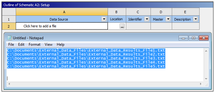
Press Ctrl+V to add the files.
In the Properties pane, set the properties of the files.
If the files are of the same or similar format, you can multi-select the files to set common properties.
When you multi-select the files in the Outline pane, you see:
A value when that value is the same for all selected files.
A blank field when values differ between selected files.
A yellow field when a value is required, but is not currently specified for any of the files.
If you edit any field in the Properties pane when multiple files are selected, your change is applied to all files.
If the X, Y, Z locations of the source points is common between all the files, you can make use of the main file designation. By designating a main file, all other files use that file's values for the X, Y, Z locations. This leads to faster user interface set up, as well as much faster mapping times as the mapping weight calculations need to be done only once and then are shared for all child files.
Use the Table pane (which is populated from the Format String field in the Properties pane) to specify the Column data in the file.
You can multi-select the files to fully populate the Table pane. You can span data from all selected files and use various right-mouse button actions to efficiently define the column data.
In the Outline pane, multi-select the desired files.
In the Table pane, sort the table by Column to order the file data. For example, if you have four data fields and the first three specify the X, Y, Z locations, sorting by column places the remaining data-field entries together at the bottom of the column.
Select the first row to be changed by clicking on the row number (which is in the table boundary).
Press and hold Shift key.
Select the last row to be changed by clicking on the row number.
Right-click anywhere over the selected cells, select from the context menu, and set the desired data type.
Repeat as required to set the data units using the option.
Tip: If or are not available, ensure that your mouse cursor is over the body of the table, not on the table boundary.
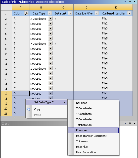
Select and copy the cell entries in the Combined Identifier column that correspond to the multiple data sets (using Ctrl+C or right-click and select ). These data-identifier strings are used to specify which data set will be imported at each load step inside Mechanical.
Link the External Data system into the desired Mechanical system/cell.
Update the External Data system.
Edit (or, if editor is already open, refresh) the Mechanical system.
Set the required Number Of Steps in the Mechanical Analysis Settings object. Set the step end times as required (you can copy and paste).
As needed, create the desired Imported Load/Thickness in Mechanical.
Select the Imported Object, then paste the data identifier text into the appropriate cells inside the Data pane on the imported object.
As required, copy and paste the desired step end times on the Analysis Settings Object and the Imported Data Object (in the Analysis Time(s) column).
Right-click Import Load to invoke the mapping calculations.
After mapping has completed, you can review the various mappings by adjusting the Active Row entry. The graphics render a contour plot of the imported data at the specified row. Additionally, this data can be exported out of Mechanical by right-clicking the tree object and selecting .
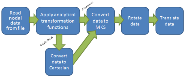
Analytical transformation options can be applied to the source nodal locations. You can enter constant or functional values that are applied to the x, y, and z (or r, theta, z for cylindrical) values read from the input file from within the External Data User Interface. For a complete list of supported functions, go to Expressions, Functions, Quantities, and Units. The order of operations for conversion of the original node locations into a format the common mapping utility uses must be taken into consideration when setting up analytical transformation functions, rotation, and translation information.
The nodal data, as well as any unit system information, is read into the common mapping utility. If any nodal analytical transformation values or functions are provided, they are applied directly to the nodal coordinates as they are read in from the file. If the data is provided in a cylindrical system, it is converted into Cartesian coordinates. Once the nodes are in Cartesian, all nodal data is converted into MKS, so that the mapping utility stores all data in the same unit system. If any rotational information is provided, this is applied next, followed by any translations.
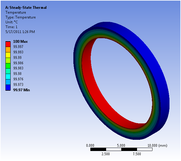
The following example takes nodal data, written in a cylindrical system, from a ring with an inner radius of 8 mm and an outer radius of 10 mm and allows an analytical transformation value to be applied to the radius of the source data, such that it aligns with a smaller ring with an inner radius of 7.2 mm and an outer radius of 9 mm.
Thermal results on an expanded or stretched ring (inner radius is 8 mm and outer radius is 10 mm)
Sample cylindrical nodal data:
| Node Number | Radius (mm) | Theta (radians) | Z Location (mm) | Temperature (–C) |
|---|---|---|---|---|
| 1 | 8.914523065 | –0.247535105 | 1.6 | 99.983 |
| 2 | 8.914523065 | –0.247535105 | 1.2 | 99.984 |
| 3 | 8.914523065 | –0.247535105 | 0.8 | 99.984 |
| 4 | 8.914523065 | –0.247535105 | 0.4 | 99.983 |
| 5 | 8.917873803 | –0.192647608 | 1.6 | 99.983 |
| 6 | 8.917873803 | –0.192647608 | 1.2 | 99.984 |
| 7 | 8.917873803 | –0.192647608 | 0.8 | 99.984 |
| 8 | 8.917873803 | –0.192647608 | 0.4 | 99.983 |
| 9 | 8.927166575 | –0.137916029 | 1.6 | 99.983 |
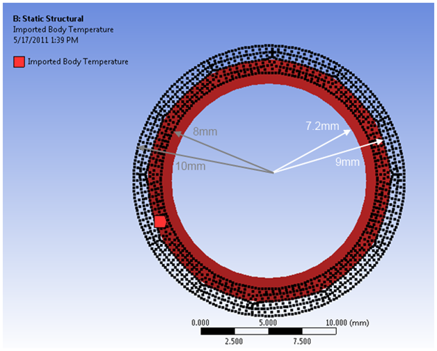
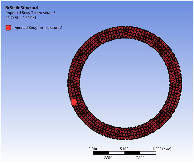
If we simply import the nodal data, you can see how the source nodes are not contained within the target volume.
Imported temperature load with unmodified source points displayed:
Within the External Data System user interface, you can enter analytical transformation values as either constants, or as functions of x, y, or z. For our example, we want to scale the source radius (that is, X Coordinate) by 90%.
Applying a constant analytical transformation scale factor to the radius (that is, X Coordinate) of the cylindrical source nodal locations:
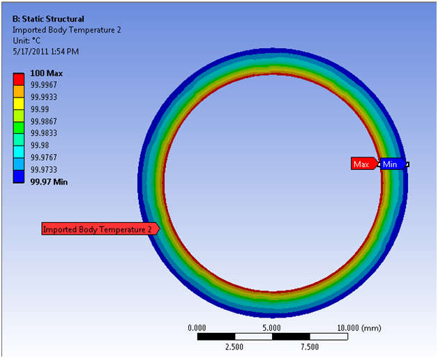
Updating the schematic and looking at the imported load we see the analytical transformation value has been applied to the nodal locations and now coincides with the target model.
Imported temperature load with "transformed" source points displayed:
Importing the load generates the following imported load:
You can use Workbench to perform coupled simulations using multiple analysis or component systems. The External Data system may be used as a source of static (that is, unchanging) data for other co-simulation participants such as Ansys Forte or Ansys Mechanical, as described in the System Coupling User 's Guide
External Data System and System Coupling Configuration
Each External Data system that is connected to the System Coupling system is represented as a coupling participant in the System Coupling setup. The name of this participant is the name of the External Data system specified in the Workbench Project Schematic. Since the External Data system acts as a source of static data, it can only be defined as the source in System Coupling's Data Transfer definition.
Each input file added to an instance of the External Data system is represented as a coupling region for the associated coupling participant in the System Coupling setup.
Supported Input File Formats
To use the External Data system as a coupling participant, the Ansys external data file format should be used. For information regarding use of this file format, see Importing an Ansys External Data File as Input.
Supported Data Types
Data types provided by external data that are currently consumable by the System Coupling system include temperature and heat rate.
In the XML file transferred from the External Data system to System Coupling, if the units of the coordinates in are not all consistent, an error is reported.