


Size Functions and Scoped Sizing provide control over how the mesh size is distributed on a surface or within the volume. They provide accurate sizing information for the mesh distribution and precise refinement control.
Scoped sizing differs from size functions in how the sizing can be associated with objects or zones, respectively. Scoped sizing may be applied to model features such as faces, edges, face zone labels or unreferenced face or edge zones. You can optionally select the type of object (geom, mesh) while applying scoped sizing. Scoped sizing can be defined on individual zone or object entities by selecting from a list or using wildcards (*). For convenience, your scoped sizing definitions can also be saved to a file (*.szcontrol) which can be read in and reused for similar models having the same naming conventions.
The size field is computed based on the size functions and/or scoped sizing defined. You can remesh surfaces and edges based on the size field. The CutCell mesher also uses the size field to refine the initial Cartesian mesh.
Important: Size functions can be computed only for triangulated zones.
For zones comprising non-triangular elements, you can triangulate
the zones manually before computing the size functions. Alternatively,
you can use the command triangulate-quad-faces? before computing the size functions. This command identifies the
zones comprising non-triangular elements and uses a triangulated copy
of these zones for computing the size functions.
When the size functions or scoped sizing is used, the mesh distribution is influenced by
The minimum and maximum size values
The growth rate
The size source which can be any one of the following:
Edge and face curvature, based on the normal angle variation between adjacent edges or faces.
Edge and face proximity, based on the number of element layers created in a gap between edges or faces.
The body of influence defined.
Constant user-defined sizes through hard and soft behaviors. The curvature, proximity, body of influence, and soft size functions have soft behavior. The meshed and hard size functions have hard behavior.
This chapter contains the following sections:
The following size functions or scoped sizing controls are available:
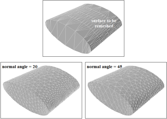
The curvature size function/scoped control computes edge and face sizes using their size and normal angle parameters, which are either automatically computed or defined.
The curvature sizing is defined by the following parameters:
Min, Max size
Growth rate
Normal angle
The curvature size function/scoped control
uses the normal angle parameter as the maximum allowable angle that
one element edge may span. For example a value of 5 implies that a division will be made when the angle change along
the curve is 5 degrees; hence, a 90 degree arc will be divided into
approximately 18 segments.
Note: As the curvature values are computed approximately using edges and face facets, there may be some numerical errors, especially when face facets are excessively stretched.
Figure 7.1: Use of Curvature Sizing shows an example where the surface has been remeshed based on a curvature size function. The change in normal angle and growth rate controls the size distribution.
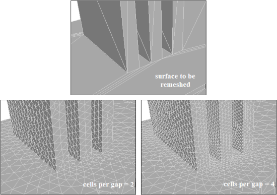
The proximity size function/scoped control computes edge and face sizes in ‘gaps’ using the specified minimum number of element layers. For the purposes of specifying proximity sizing, a ‘gap’ is defined in one of two ways:
The area between two opposing boundary edges of a face
The internal volumetric region between two faces
The proximity sizing is defined by the following parameters:
Min, Max size
Growth rate
Cells per gap
Figure 7.2: Use of Proximity Sizing shows an example where the surface has been remeshed based on a proximity size function. The change in the cells per gap and growth rate parameters control the size distribution.
Note: For proximity size functions, the number of cells per gap can be a real value, with a minimum of 0.01. This has the effect of increasing the size of face elements located farther away from edges, and stretching face elements with larger sizes along side faces, or gaps, thereby reducing the overall face count, and ultimately the cell count.
Additional options for defining the face proximity sizing are as follows:
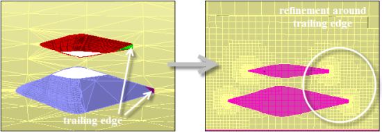
The Face Boundary option enables you to compute the shell proximity (edge-edge proximity within each face). The proximity between feature edges on the face zones selected is computed. This option is particularly useful for resolving trailing edges and thin plates without using the hard size function.
The example in Figure 7.3: Use of the Face Boundary Option for Face Proximity shows the use of this option for a blade configuration. Though the normals on the blade surface point outward, the cells across the trailing edges will be refined based on the proximity size function defined for the trailing surfaces when the Face Boundary option is enabled.
Note: The Face Boundary option works on the internally extracted boundary edge zones of the face zones. Edge zones extracted in the meshing mode/CAD imported edges will not be considered for the proximity calculation.
The Face - Face option enables you to compute the proximity between two faces in the face zones selected. When the Face - Face option is enabled, additional options for ignoring self proximity (Ignore Self) and ignoring the face normal orientation (Ignore Orientation) are also available.
The Ignore Self option can be used with the Face - Face option in cases where self proximity (proximity between faces in the same face zone) is to be ignored. This option is disabled by default.
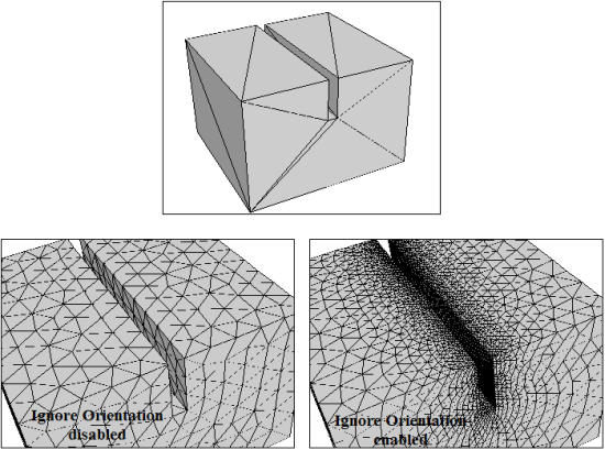
The Ignore Orientation option can be used to ignore the face normal orientation during the proximity calculation. This option is enabled by default. In general, the proximity depends on the direction of face normals. An example is shown in Figure 7.4: Use of the Ignore Orientation Option for Face Proximity. The normals on the grooved box point inward. With only the Face - Face option, the proximity size function does not refine the surface along the entire groove length. When the Ignore Orientation option is enabled along with the Face - Face option, the surface will be refined along the groove length.
Note: You must select at least one of the Face Boundary and Face - Face options; otherwise, an error will be reported.
The edge proximity size function depends only on the distance between the edges, irrespective of their association with a face zone or the orientation of the face zones associated with the edge zones.
Important: When using a proximity sizing in certain geometries (with angle > 30 degrees or comprising extended region of non-intersecting faces), the proximal face zones may not be detected and may result in a warning message. In such cases, split the proximity sizing into multiple proximity scoped sizing controls.
Tip: When using a proximity size function with geometries having a very large number of small feature edges, you can speed up the calculation and reduce memory requirements by enabling Quick Edge Proximity. Go to > , select from the Categories drop down list, and check Quick Edge Proximity. Accuracy will be reduced when Quick Edge Proximity is enabled.
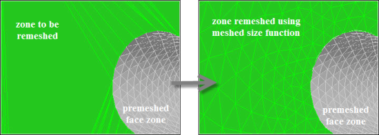
The meshed size function/scoped control enables you to set the size based on existing sizes. This provides gradation between the minimum and maximum size based on the specified growth rate.
The default behavior for the meshed size function/scoped control is soft, allowing other hard sizes or locally smaller sizes to override it. You can enable Hard Meshed Size Functions by going to the menu, and selecting Size Functions in the drop down list.
Note: In Release 15.0 and earlier, the behavior for the meshed size function/scoped control was hard. This behavior is saved with the mesh file. Therefore, when reading a mesh saved using such a release, the Hard Meshed Size Functions control may be enabled.
The meshed sizing is defined by the growth rate.
In Figure 7.5: Use of Meshed Sizing, the face zone is remeshed based on the premeshed face zone indicated.
The hard size function/scoped control enables you to maintain a uniform size based on the size specified, while the growth rate from the defined size influences the size on adjacent zones. The hard sizing will override any other size function specified.
The hard sizing is defined by the following parameters:
Min Size
Growth rate
Important:
It is recommended to not have two hard sizes next to each other as the mesh size transition between the two will not be smooth.
If two hard sizes are applied at the same location, the latter will be honored. The smaller size rule does not apply in this case.
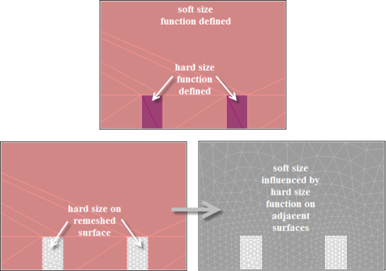
The soft size function/scoped control enables you to set the maximum size on the selected zone, while the specified growth rate from the defined size influences the size on adjacent zones. When the soft sizing is selected for edges and/or faces, the size will be affected by other size functions/scoped controls. The minimum size on the zone will be determined based on the influence of other size functions/scoped controls, else a uniform size will be maintained. In other words, a soft sizing is ignored in a region where other sizing controls specify smaller sizes.
The soft sizing is defined by the following parameters:
Max size
Growth rate
In the example in Figure 7.6: Use of Soft Sizing, the minimum size is determined by the hard sizing applied on the smaller face zones indicated, and maximum size is limited by the soft sizing applied.
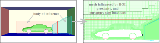
The body of influence size function/scoped control enables you to specify a body of influence (that is, a region for sizing control). The maximum mesh size will be equal to the specified size within the body of influence. The minimum size will be determined based on the influence of other size functions/scoped controls. An example is shown in Figure 7.7: Use of Body of Influence Sizing.
Note: The set of face zones selected to define the body of influence should constitute a geometrically closed region. If an open region is used as a body of influence, the sizing will be processed as a soft sizing.
The body of influence sizing is defined by the following parameters:
Max Size
Growth rate
In Figure 7.7: Use of Body of Influence Sizing, the mesh is generated based on the body of influence sizing defined. The finer mesh size is obtained due to other size functions (for example, curvature, proximity) defined in addition to the body of influence size functions.
Important:
In case of multiple non-intersecting closed bodies, a single BOI size function/scoped sizing control can be set up. The sizing can be scoped to the set of face zones comprising the respective bodies.
In case of multiple intersecting closed bodies for scoping the same BOI sizing, you need to create separate BOI size functions/scoped sizing controls for each geometric body.
Note: When using BOIs with periodic boundaries, if the BOI extends outside the domain, it may cause unnecessary refinement.
Size functions can be defined using the Size Functions dialog box. Right-click on Model in the tree and select Functions... from the Sizing menu. The generic procedure to define size functions is as follows:
Ensure that the global controls are set as required. The relevant size function parameter values (minimum and maximum size, growth rate) will be updated based on the global controls specified.
Enable Face Zones (or Edge Zones) as appropriate.
Select the boundary zones (or the edge zones) for which the size function is to be defined in the Boundary Zones (or Edge Zones) selection list.
Note: All boundary face zones and edge zones included in the global domain are available for defining size functions, even if a local domain has been activated.
Select the appropriate size function type in the Size Function Type drop-down list in the Define Size Function group box.
Enter an appropriate size function name in the Name field or leave the field blank if you want to have the name generated automatically. In this case, the Name will be assigned according to the zone type (face or edge) and the size function type. (For example, face-curvature-sf-5 indicates that the curvature size function is defined for face zones. The size function ID is 5.)
Specify the size function parameters applicable for the selected size function as appropriate and click Create.
The defined size function will be available in the Size Functions list.
You can create default size functions based on face and edge
curvature and proximity using the Create Defaults option in the Size Functions dialog box. Alternatively,
you can use the command /size-functions/create-defaults to create the default size functions.
The following size functions will be defined:
Curvature size function on all edge zones, with the global minimum and maximum sizes and growth rate, and a normal angle of
18.Curvature size function on all face zones, with the global minimum and maximum sizes and growth rate, and a normal angle of
18.Proximity size function on all edge zones, with the global minimum and maximum sizes and growth rate, and the cells per gap set to
3.Proximity size function on all face zones, with the global minimum and maximum sizes and growth rate, and the cells per gap set to
3.
When the Create Defaults option is used after the default size functions have been created, the previous definitions will be updated based on any changes to the global minimum and maximum sizes and growth rate.
Scoped sizing controls can be defined using the Scoped Sizing dialog box. Right-click on Model in the tree and select Scoped... from the Sizing menu. The generic procedure for defining scoped sizing controls is as follows:
Set the global scoped sizing controls as required. The relevant local control parameter values (minimum and maximum size, growth rate) will be updated based on the global values specified.
Select the appropriate scoped control type in the Type drop-down list in the Local Scoped Sizing group box.
Enter an appropriate name in the Name field.
Specify the local sizing parameters applicable for the selected scoped control type as appropriate.
Select the scope for the scoped control defined from the Scope To drop-down list. Additionally, select the Object Type (Geom and/or Mesh) and specify a suitable pattern in the Selections field.
You can also click
 to open the Scope
dialog box and select the objects, face zone labels, face zones, or edge zones for
defining the size control scope.
to open the Scope
dialog box and select the objects, face zone labels, face zones, or edge zones for
defining the size control scope.Click .
The defined size control will be available in the Controls list.
You can validate the defined scoped sizing
controls using the command /scoped-sizing/validate. An error will be
reported if the scoped sizing controls do not exist or the scope for one (or more) controls is
invalid.
The size controls file (*.szcontrol) contains the scoped sizing control definitions. The control name and type, and the scope of the control will be included in the size control file along with global size parameters.
To read a size controls file, click in the Scoped Sizing dialog box to invoke the Select File dialog box and specify the name of the file
to be read. Alternatively, you can use the /scoped-sizing/read command and specify the name of the file to be read.
To write a size controls file, click in the Scoped Sizing dialog box to invoke the Select File dialog box and specify the name of the file
to be written. Alternatively, you can use the /scoped-sizing/write command and specify the name of the file to be written.
The size field can be computed based on the defined size functions
and scoped sizing controls by clicking in the Size Functions dialog box or the Scoped Sizing dialog box. Alternatively, use the command /size-functions/compute or /scoped-sizing/compute to compute the size field.
Important: If the size field has been computed in the current session, sizes will be based on the computed size field. You cannot define additional size functions or scoped sizing controls, or modify the current sizes without deleting the size field.
Size field files contain the size function definitions based on the parameters specified.
Select the File/Read/Size Field... menu
to read a size field file. This will invoke the Select File dialog box, where you can specify the name of the size field file
to be read. Alternatively, you can use the /file/read-size-field command and specify the name of the file to be read.
Important: If a size field file has been read in the current session, sizes will be based on the size field read. You cannot define additional size functions or scoped sizing controls, or modify the current sizes without deleting the size field.
Select the File/Write/Size Field... menu
to save a size field file based on the parameters set. This will invoke
the Select File dialog box, where you can specify
the name of the size field file to be written. Alternatively, you
can use the /file/write-size-field command
and specify the name of the file to be written.
Additional size field filtering options are available after the size field is computed/read. These options are available in the Size Field Filters dialog box.
Click in the Size Functions or Scoped Sizing dialog box to open the Size Field Filters dialog box.
You can specify a scale factor to filter the size output from the size field, without deleting and recomputing the size field. The scaling filter can be applied as follows:
Specify an appropriate value for Factor, Min and Max (for Scale).
Click .
Alternatively, you can use the command
/size-functions/set-scaling-filter, and specify the scale factor, minimum and maximum size values.You can apply periodicity to the size field, without deleting and recomputing the size field as follows:
Click to open the Periodicity dialog box.
Select the type of periodicity (Rotational or Translational).
For translational periodicity, specify the shift vector components You can also click and select 2 nodes to set up the shift vector for translational periodicity.
For rotational periodicity, enter an appropriate value for Angle.
For rotational periodicity, specify the pivot point and axis of rotational periodicity.
You can also select 1–6 nodes and click to set up the pivot point and axis of rotation for rotational periodicity as follows:
If only 1 node is selected, the pivot point is at the node location and the axis of rotation is the global z-axis.
For 2 nodes, the pivot point is at the midpoint of the nodes selected and the axis of rotation is the global z-axis.
For 3 nodes, the pivot point is at the first node selected. The axis of rotation is the local z-axis normal to the plane defined by the three points, the positive direction is determined by the right-hand rule.
For 4, 5 or 6 nodes, the first 3 points define a circle. The pivot point is at the center of the circle. The axis of rotation is the local z-axis normal to the circular plane, the positive direction is determined by the right-hand rule.
Click to enable Periodicity in the Size Field Filters dialog box.
Note:If periodicity is set up prior to computing the size-field, the Periodicity filter will be enabled when the size-field is computed.
Alternatively, you can set up the periodic boundary using the Make Periodic Boundaries dialog box. See Creating Periodic Boundaries for details.
> >
You can also use the command
/size-functions/enable-periodicity-filterand specify the angle, pivot, and axis of rotation. If periodicity has been previously defined, the existing settings will be applied.
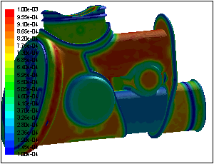
Before computing the size field, you can check if the global minimum and maximum sizes are suitable locally. After computing the size field, you can set the selection filter to size and use the probe to determine local size or make a contour plot of the sizing on any surface
You can display the contours of size using the options in the Size Functions dialog box as follows:
Select the face zones in the Boundary Zones selection list in the Size Functions dialog box.
Specify appropriate values for Min and Max in the Contours group box.
Click (in the Contours group box).
Alternatively, after selecting the face zones, use the hot key Ctrl+T (Miscellaneous Tools), then Ctrl+C to draw size contours.
Figure 7.8: Contours of Size shows the display of contours of size on the selected face zones after the size field has been computed or read
A visual indication of mesh size is also available using the mouse probe.
- Size selection filter
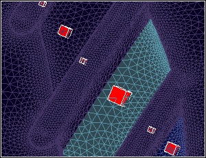
If the selection filter is set to size (hot key Ctrl+Y), right-click at the required locations to see the size boxes indicating the mesh size. See Figure 7.9: Display of Mesh Size Based on Size Field.
- Preview sizes
Alternatively, after selecting the face zones, use the hot key Ctrl+T (Miscellaneous Tools), then Ctrl+P to preview sizes on the selected zones. You can set the minimum and maximum size values in the Preview Sizes dialog box.
The size field can be used to remesh surfaces and edges. The CutCell mesher also uses the size field to refine the initial Cartesian mesh.
Remeshing Surfaces
The generic procedure for remeshing surfaces is as follows:
Select the surface(s) to be remeshed. You can use the graphics select tools or select from a list in a dialog box.
Use the hotkey Ctrl+Shift+R or click the Remesh button to open the Zone Remesh dialog box.
Choose the appropriate Sizing from the drop down list and set other parameters as necessary.
Click Remesh.
For more control of surface remeshing parameters, use the Surface Retriangulation dialog box as follows:
> >
Select the surfaces to be remeshed in the Face Zones list.
Enable Size Function in the Face Remesh Options group box and click the Specify button to open the Size Functions dialog box and check that the size functions are appropriate. See Defining Size Functions.
Alternatively, ensure that the size field has been computed or read in.
Set the other options for face remeshing as appropriate.
Click Remesh.
Important: Edge zones associated with face zones are not remeshed implicitly. If you have feature edge zones associated with the surface being remeshed, you need to remesh them before remeshing the face zones.
Remeshing Edges
The generic procedure for remeshing edges is similar to the above procedure for surfaces. Use the hotkey Ctrl+Shift+Z, or click the Edge Zone restriction button, to constrain the selection to edge zones only.
For more control of edge remeshing parameters, use the Feature Modify dialog box as follows:
> >
Ensure that the edge zones are extracted as required.
Select the edges to be remeshed in the Edge Zones list in the Feature Modify dialog box.
Select Remesh in the Options list and select Size Function in the Method drop-down list.
Make sure the size functions are defined as appropriate in the Size Functions dialog box (see Defining Size Functions). Alternatively, ensure that the size field has been computed or read in.
Click Apply.
Refining the CutCell Mesh
The CutCell mesher uses the size functions/size field to refine the initial Cartesian mesh as described in The CutCell Meshing Process.