


Object-based meshing is the recommended meshing approach with which you can generate a tetrahedral, hexcore, or polyhedral volume mesh, with or without inflation layers. In this approach, you first create a conformal, connected surface mesh on all the objects to be meshed. The surface mesh, and material points if required, are then used to identify the regions to be filled with the volume mesh.
This chapter describes the processes used to create a conformal, connected surface mesh. Steps to create the volume mesh are described in Object-Based Volume Meshing. Refer to Objects and Material Points for more information on meshing objects.
Important: Ensure that the model is suitably scaled during import and the global minimum size is at least 0.01 to avoid numerical problems during mesh generation.
The tools to complete the object-based surface meshing steps are found in the context-sensitive menus in the Outline View or in the onscreen tools and hotkeys. Instructions are described in the following sections.
In principal, there are two basic workflows to create a conformal, connected surface mesh from an unconnected assembly.
Note: It is assumed that objects are already created upon CAD import. Object management, if necessary, is described in Objects.
Single fluid volume using Wrapper based workflow
The basic Wrapper based workflow for a single fluid volume simulation follows these steps:
Import the CAD model using the CAD Faceting tessellation option.
Geometry objects are created. See Importing CAD Files for additional information.
Define sizing and compute the size field.
Scoped Sizing is recommended to apply individual size controls on specific objects as required. See Defining Scoped Sizing Controls for additional information.
Define material points to assist in identifying the fluid volume.
See Material Points for additional information.
Check and fix the geometry, particularly gaps.
You can use the context menu > , accessible from any Geometry object, to assist in finding any geometry issues. See Diagnostic Tools for additional information.
Missing geometry objects may be constructed as described in Preparing the Geometry.
Define periodic boundaries, if applicable.
See Creating Periodic Boundaries for additional information.
Wrap the model.
Step through the options available in the context menu. See The Wrapping Process for details.
Check the mesh and improve the quality, if necessary.
You can use the context menu > , accessible from any mesh object.
Complex topology using Join and Intersect based workflow
The basic Join/intersect based workflow for complex topology such as CHT simulation, follow these steps:
Import the CAD model using the CFD Surface Mesh tesselation option.
Mesh objects are created. See Importing CAD Files for additional information.
Note: If the assembly has already been connected (for example, using Share Topology operations in Ansys DesignModeler or SpaceClaim), it is sufficient to just import the CAD using the One object per file and CFD Surface Mesh options.
Check the mesh and fix the connectivity, if necessary.
You can use the context menu > , accessible from any mesh object.
Check and fix the geometry, particularly gaps.
You can use the context menu > , accessible from any Geometry object, to assist in finding any geometry issues. See Diagnostic Tools for additional information.
Missing geometry objects may be constructed as described in Preparing the Geometry.
Merge all objects to a single object using the Merge option in the context menu.
Connect all bodies.
You can use the Join/Intersect context menu or the onscreen tools for Join or Intersect. See Connecting Objects for additional information.
Optionally define sizing, compute the size field and remesh if necessary.
Remesh is recommended as it often reduces mesh count and improves quality while maintaining sufficient mesh density. You can use the Remesh Faces context menu or the onscreen tools.
Computing a size field is necessary only if you choose to remesh. Scoped Sizing is recommended to apply individual size controls on specific objects as required. See Defining Scoped Sizing Controls for additional information.
Define periodic boundaries, if applicable.
See Creating Periodic Boundaries for additional information.
Check the mesh and improve the quality, if necessary.
You can use the context menu > , accessible from any mesh object.
When the surface mesh is conformally connected and of sufficient quality, proceed to generate the volume mesh as described in Object-Based Volume Meshing.
When the geometry is imported from CAD, there may be a number of gaps and the faceted geometry may be disconnected. Though operations such as merging nodes and faceted stitching can be used to partially connect the model, some gaps may remain and features may be lost.
You may want to perform tasks such as create a wind tunnel or far-field domain, close annular gaps, create capping surfaces for inlets or outlets, or create groups of zones for models with a large number of zones. Right-click on Model in the tree and select the appropriate option from the menu to access the options to perform such operations.
The bounding box tool can be used to create a wind tunnel or far-field domain for the imported geometry. A geometry object can be created for the bounding box surface created. You can also use the bounding box tool to create a body of influence to be used for defining size functions. See Using the Bounding Box Dialog Box for details on the options for creating a bounding box. Right-click on Model in the tree and select > to open the Bounding Box dialog box.
See Creating a Cylinder/Frustum to create a cylindrical or annular surface to close radial gaps in the geometry. A geometry object can be created for the surface created. Right-click on Model in the tree and select > to open the Cylinder dialog box.
Figure 7.17: Closing a Radial Gap shows an example where a radial gap is closed using a cylindrical surface.
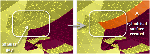
Select 3 Arc, 1 Height Node in the Options list.
Click and select 3 nodes on one circle and one (height node) on the other across the radial gap.
Enter an appropriate value for Edge Length.
Enable Create Object and disable Caps.
Click Create.
The patching tools enable filling of unwanted holes in the geometry. A hole may be bounded by either free edges or feature edges. Use the patching tools to:
patch holes associated with free faces in multiple zones
fill punched holes in a single zone
cap inlets/outlets and assign the appropriate zone type
patch other complex shapes to close gaps including sharp angles and small pockets in the geometry using the loop selection tools
Use the patching tools to locate and fix the major holes in the geometry. If you miss any holes, you can fix them later using the hole detection feature. See Fixing Holes in Objects for details.
When the patching tools are used, by default, the new faces are added to a new face zone and are remeshed. These options are available in the Patch Options group in the ribbon.
Remesh enables the automatic remeshing of the patched area.
Separate enables the creation of a separate face zone/object for the new faces created. Additional options for object/zone granularity and type are available in the Patch Options dialog box.
The Patch Options dialog box contains options for object/zone granularity and type and is available when the Separate option is selected. Specify the object/zone granularity as follows:
Select New Object to create a new object for the face zones. Specify the object name and a label name. If the label name is not specified, the object name will be used as the label name. Face zone names will be the same as the label names. Select the Object Type and Zone Type from the lists.
Select Add to Object to add the face zones to an existing object. Select the object and specify a label name. If the label name is not specified, the default name patch:# (# indicates the ID) will be used. Face zone names will be the same as the label names. Select the Zone Type from the list.
Select Add to Unreferenced to create unreferenced face zones. Select the Zone Type from the list. The default name patch:# (# indicates the ID) will be used for the zone name. These zones will be available in the Unreferenced branch of the tree.
Using Edge/Node Selections
Select edges/nodes in the graphics window to fix the holes in the geometry.
Fixing holes by selecting edges.
Set the patching options in the Patch Options group in the ribbon.
Select the edge filter (
 or hot-key Ctrl+E) and select any edge on the hole boundary. You can select either free
edges or feature edges.
or hot-key Ctrl+E) and select any edge on the hole boundary. You can select either free
edges or feature edges.Click
 or
press F5 to create the surface that closes the hole.
or
press F5 to create the surface that closes the hole.If the Separate option is enabled, set the object/zone granularity and type in the Patch Options dialog box (Using the Patch Options Dialog Box). If the Remesh option is enabled, the face zones will be remeshed.
Click in the Patch Options dialog box.
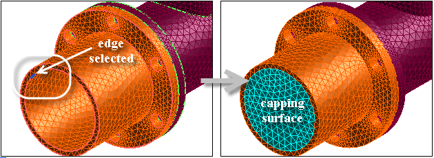
Figure 7.18: Creating a Surface Using an Edge shows an example where the capping surface is created by selecting an edge on the existing object.
Fixing holes by selecting nodes.
Set the patching options in the Patch Options group in the ribbon.
Select the node filter (
 or hot-key Ctrl+N) and select the nodes around the hole.
Press
or
F5 to create the surface that closes the hole.If the Separate option is enabled, set the object/zone granularity and type in the Patch Options dialog box (Using the Patch Options Dialog Box). If the Remesh option is enabled, the face zones will be remeshed.
Click in the Patch Options dialog box.
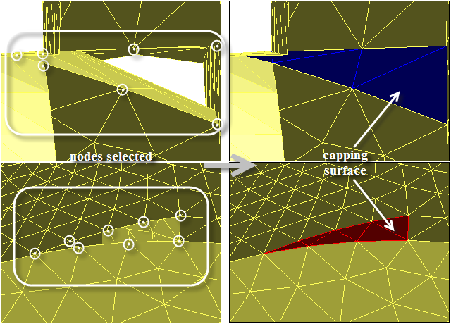
Figure 7.19: Creating a Surface Using Nodes shows an example where the capping surfaces are created by selecting nodes on the existing object.
Patching Multiple Holes in a Single Zone
All holes associated with free edges or punched holes in a
single zone can be closed in a single patching operation using the hot-key Ctrl+R (![]() ).
).
Set the patching options in the Patch Options group in the ribbon.
Select the appropriate entity for the operation:
For patching holes with free faces, select the appropriate face zones in the graphics window.
For patching punched holes, select a face adjacent to a hole in the face zone.
Note: Punched holes can be closed only in a single face zone having finite thickness. There should be no free faces in the face zone being patched.
Click
 or use the
hot-key Ctrl+R.
or use the
hot-key Ctrl+R.If the Separate option is enabled, set the object/zone granularity and type in the Patch Options dialog box (Using the Patch Options Dialog Box). If the Remesh option is enabled, the face zones will be remeshed.
Click in the Patch Options dialog box.
The loop selection tool can be
accessed by clicking ![]() in the graphics window or using the hot-key Ctrl+Shift+L. This tool provides additional options, such as using fewer node selections,
for creating the capping surface. You can also select positions to define the loop.
in the graphics window or using the hot-key Ctrl+Shift+L. This tool provides additional options, such as using fewer node selections,
for creating the capping surface. You can also select positions to define the loop.
The following selection options are available:
In the first group of tools, choose how the path between selected nodes/positions is defined - by edges, feature, boundary, or direct path. Click
 to switch between selecting nodes or positions to define the loop.
The second group of icons is used to select open or closed loop. Then, for closed loop mode, you can choose how the path between the first and last nodes is defined - by edges, feature, boundary, or direct path.
After making the necessary selections, click ![]() or use the hot-key Ctrl+K in the Loop Selection mode to open the Create Cap dialog
box.
or use the hot-key Ctrl+K in the Loop Selection mode to open the Create Cap dialog
box.
The Create Cap dialog box contains options for object/zone granularity and type and for remeshing the capping surface.
Specify the object/zone granularity.
Select New Object to create a new object for the face zones. Specify the object name and a label name. If the label name is not specified, the object name will be used as the label name. Face zone names will be the same as the label names. Select the Object Type and Zone Type from the lists.
Select Add to Object to add the face zones to an existing object. Select the object and specify a label name. If the label name is not specified, the default name patch:# (# indicates the ID) will be used. Face zone names will be the same as the label names. Select the Zone Type from the list.
Select Add to Unreferenced to create unreferenced face zones. Select the Zone Type from the list. The default name patch:# (# indicates the ID) will be used for the zone name. These zones will be available in the Unreferenced branch of the tree.
Enable Remesh to remesh the capping surface created.
Click in the Create Cap dialog box.
For the list of hot-keys associated with the options in the Loop Selection toolbar, refer to Appendix C: Shortcut Keys.
You can define user-defined groups to better handle large models. The options for manipulating user-defined groups are available in the User Defined Groups dialog box. Right-click on Model in the tree and select to open the User Defined Groups dialog box.
You can create a face group and an edge group comprising the face zones and edge zones included in the specified objects using the options in the Zone Group group box in the Operations tab in the Manage Objects dialog box. You can activate a particular group using the Activate option in the User Defined Groups dialog box.
Additionally, a face zone group is automatically created when a mesh object is created using the Sew operation. This face zone group is prefixed by _mesh_group, and enables easy selection of mesh object face zones for various operations (improve, smooth, and so on).
Note: When an object is deleted along with the face and edge zones comprising the object, the corresponding groups will also be deleted.
Important: You cannot create a new group having the name global, or having the same name as one of the default groups.
The options in the Diagnostic Tools dialog box enable you to find and fix problems in boundary meshes, or display boundary mesh statistics, of selected objects. The Diagnostic Tools dialog box is accessed by selecting the appropriate option from the Diagnostics sub-menu available by right-clicking on any geometry or mesh object selected in the Outline View.
Diagnostic tools are available for the following:
finding and fixing Geometry problems, such as gaps or intersections between objects.
finding and fixing Connectivity problems in the surface mesh, such as free or multi-connected edges, and overlapping or intersecting faces.
finding and fixing Quality problems in the surface mesh.
A Summary table of mesh statistics can be obtained using the Summary button at the bottom of the Diagnostic Tools dialog box, or from the context-sensitive menu on any geometry or mesh object selected in the tree.
Note: When selecting Diagnostics... from under a mesh object’s Face Zone Label, the Geometry options are not available. The dialog box contains only Face Connectivity and Quality options for the boundary zones included in the Face Zone Label.
Problems in the geometry, such as gaps or intersections can be located and fixed using the diagnostic tools. Select the objects (geometry or mesh) in the Model tree, and then select Geometry... from the sub-menu available from the context-sensitive menu.
Select the desired Issue and then set the relevant marking options. The issues that can be diagnosed are as follows:
Self Intersections
Cross Intersections
Self Face Proximity
Cross Face Proximity
Self Edge Proximity
Click Mark to identify and obtain a count of the Unvisited problems in your boundary mesh.
Click First (Next) to step through the problems individually. At each step, the identified problem region will be highlighted in the graphics window.
To correct the identified problem (if necessary), click the appropriate button in the Operations group box. You can choose to fix all identified problem areas or the area that is currently displayed.
Note: Many other geometry modification tools are available. The buttons presented in the Operations group box represent the most likely tools for the type of issue.
Problems in the surface mesh such as free or multi-connected faces, self-intersecting faces, or other problematic configurations can be located and fixed using the diagnostic tools. Select the objects (geometry or mesh) in the Model tree, and then select Connectivity and Quality... from the sub-menu available from the context-sensitive menu.
Note: If a Face Zone Label is selected under a mesh object, the Diagnostics... menu will not have any submenu choices, but will open directly with Face Connectivity and Quality options available.
Select the boundary zones to be examined.
Select All to select the boundary zones from a list including all boundary face zones available.
Select Unmeshed to select the boundary zones from a list of the unmeshed tri zones available. The unmeshed zones are those that are not connected to a volume mesh.
On the Face Connectivity tab, select the desired Issue and then set the relevant marking options. The issues that can be diagnosed are as follows:
Free
Multi
Self Intersections
Self Proximity
Duplicate
Spikes
Islands
Steps
Slivers
Point Contacts
Invalid Normals
Note: Zone-specific or scoped prism settings should be applied prior to using this option.
Leaks
Deviation
Click Mark to identify and obtain a count of the Unvisited problems in your boundary mesh.
Click First (Next) to step through the problems individually. At each step, the identified problem region will be highlighted in the graphics window.
To correct the identified problem (if necessary), click the appropriate button in the Operations group box. You can choose to fix all identified problem areas or the area that is currently displayed.
Note: Many other mesh modification tools are available. For example, you can do Local Remesh (use the hotkey Ctrl+Shift+R) or Smooth (F6) instead of Collapse (Ctrl+J) to remove slivers. The buttons presented in the Operations group box represent the most likely tools for the type of issue.
Problems with the surface mesh quality can be located and fixed using the diagnostic tools. Select the objects (geometry or mesh) in the Model tree, and then select Connectivity and Quality... from the sub-menu available from the context-sensitive menu.
Note: If a Face Zone Label is selected under a mesh object, the Diagnostics... menu will not have any submenu choices, but will open directly with Face Connectivity and Quality tabs available.
Select the boundary zones to be examined.
Select All to select the boundary zones from a list including all boundary face zones available.
Select Unmeshed to select the boundary zones from a list of the unmeshed tri zones available. The unmeshed zones are those that are not connected to a volume mesh.
On the Quality tab, set the number of quality measures and specify up to three quality measures to be used. Then select from the following quality measure options.
Skewness
Size Change
Edge Ratio
Area
Aspect Ratio
Warp
Dihedral Angle
Ortho Skew
Click Mark to identify and obtain a count of the Unvisited problems in your boundary mesh.
Click First (Next) to step through the problems individually. At each step, the identified problem region will be highlighted in the graphics window.
To correct the identified problem (if necessary), select the appropriate option in the Operations group box and click . Alternatively, you can choose to collapse or smooth all marked faces that are currently displayed.
For more information on how Fluent calculates the quality and adjusts the mesh, see the Quality Measures page.
Note: Many other mesh modification tools are available. For example, you can do Local Remesh (use the hotkey Ctrl+Shift+R) instead of Smooth (F6) or Collapse (Ctrl+J) to remove a skewed face. The buttons presented in the Operations group box represent the most likely tools for the type of issue.
A tabular summary of mesh statistics can be displayed in the console by selecting Summary from the context sensitive menu for a geometry or mesh object in the Outline View tree.
The displayed data includes the number of free-, multi-, and duplicate faces; face quality (skewness) statistics, and total number of faces and face zones. This is the same information as is displayed by clicking the Summary button in the Diagnostic Tools dialog box.
The join and intersect operations are used to connect face zone labels within a mesh object by joining overlapping faces or intersecting face zones. In case of multiple mesh objects, merge the objects into a single mesh object and then proceed to join/intersect them. For best results, it is recommended that faces be of similar size where the join or intersect operation is occurring. The process is interactive, fast, scriptable, and enables direct control over local shape and quality, and volumetric and surface overlaps.
Join/Intersect may be employed as a bottom-up strategy that enables you to build multiple sub-assemblies individually, and then connect the sub-assemblies to create the final assembly. It can be used to connect all the face zone labels within a mesh object into the final assembly in one operation. Support for part replacement without global remeshing is inherent in the process.
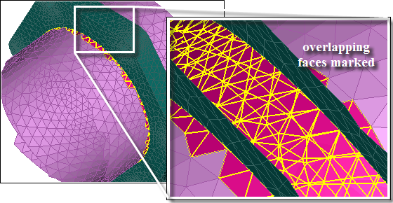
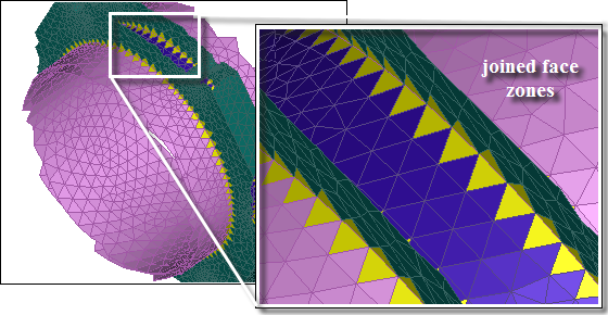
An example of the join operation is shown in Figure 7.20: Overlapping Surfaces and Figure 7.21: Connected Surfaces After Join. The overlapping area of the face zones is separated based on the parameters specified and merged into a single separated face zone after the join operation. The joined surfaces will be locally remeshed. The multi-connected faces indicate that the zones are now connected.
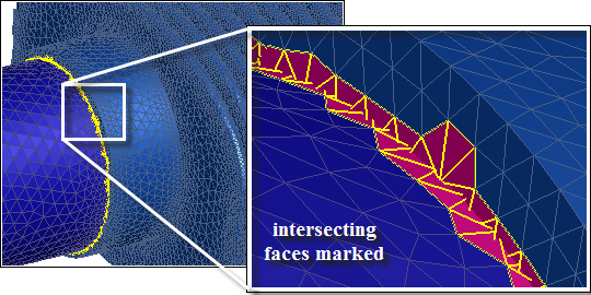
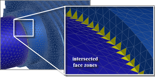
An example of the intersect operation is shown in Figure 7.22: Intersecting Surfaces and Figure 7.23: Connected Surfaces After Intersect. The intersecting faces are marked based on the parameters specified. The intersecting face zones are connected and locally remeshed.
Important: After any Join or Intersect operation, remesh is called automatically. To disable the post-remesh operation, use one of the text commands:
/objects/join-intersect/controls/remesh-post-intersection?
no |
/boundary/remesh/controls/intersect/remesh-post-intersection?
no |
The following options are available for connecting object zones:
The Join/Intersect dialog box is accessed from the context-sensitive menu under any Mesh Object, or any Face Zone Labels under a Mesh Object. For best results, the following practices are highly recommended:
Prepare clean input prior to using Join/Intersect:
Resolve free, duplicate and sliver faces using the Diagnostics tools. See Diagnostic Tools.
Identify self-proximity locations and separate it into different zones using the Diagnostics tools.
Remove gaps between the face zones to be joined to get clean contacts (overlaps). Alternatively, choose Absolute Tolerance with a value greater than or equal to the known gap if joining over smaller gaps.
Have similar mesh sizes (density) on face zones to be joined.
If wrapped meshes are used with Join, use the High option together with a scaled Size Function to produce a very fine mesh. After join, all the surfaces may be remeshed with the default size function.
The Join/Intersect dialog box can be used as follows:
Select Join/Intersect... from the context-sensitive menu available for the Mesh Object selected in the tree to open the Join/Intersect dialog box. The corresponding Face Zone Labels and Face Zones are listed.
Note: Face Zone Label represents either the collective name of the face zones in the mesh object or, in the case of conformal faceted import with one object per part, the bodies of the part.
Choose Join or Intersect in the Operation group box.
Tip: Always use the join operation first, then intersect.
For the Join operation, Skip Bad Joins is enabled by default (in the Controls group box).
Specify an appropriate value forMin. Dihedral Angle.
The Skip Bad Joins option enables joined pairs to be undone locally if a self intersection is found or if the smallest dihedral angle is less than the specified value.
In the Parameters group box, specify the decision thresholds for Angle (default is 40 degrees) and Tolerance (default is relative tolerance of 0.05, or 5% of local triangle size).
Check Absolute Tolerance to specify tolerance is in the same dimensional units as the geometry.
Use the global Join (Intersect), under the Face Zones list, to perform the selected Operation on selected Face Zones using the specified Parameters.
Alternatively, use Local controls to perform the operations on pairs of overlapping or intersecting face zones.
Local is recommended for geometry where you do not know the tolerances.
Note: Length scales of geometric features should be smaller than the local triangle size.
Click in the Local group box.
Click (and subsequently ) to step through each pair of surfaces individually. The display is automatically limited to the area of overlap/intersection since Bounded View is enabled by default.
Click to view the overlapping/intersecting faces.
Click (or ) in the Local group box to perform the selected Operation on the selected pair of surfaces.
Important:Since the join operation separates the two overlapping face zones and keeps only one separated face zone, it is possible that the separated zone may overlap with a third zone, so you should repeat the operation iteratively until no overlaps are found. The intersection operation does not separate the face zones; still, it is a good practice to repeat the operation iteratively until no intersections are found.
The surface should be inspected for self-intersections, duplicates, and so on after Join or Intersect operations using the Diagnostics tools.
Important: Quads are not supported by Join or Intersect.
Use the Join dialog box to join overlapping face zones based on selections in the graphics window.
Select the overlapping face zones in the graphics window and click
 . Alternatively, use the hot-key Ctrl+T to invoke the miscellaneous tools and then Ctrl+J to open the Join dialog box.
Specify an appropriate Tolerance (default is relative tolerance of 0.05, or 5% of local size). Alternatively, enable Absolute Tolerance and specify a value greater than or equal to the known gap.
Click . After verifying the marked faces, select the face zones to be joined again.
Click .
Click if the results of the join operation are unsatisfactory. The operation can be undone until the next mesh operation or until the Join dialog box is closed.
Use the Intersect dialog box to intersect face zones based on selections in the graphics window.
Select the intersecting face zones in the graphics window and click
 . Alternatively, use the hot-key Ctrl+T and then Ctrl+I to open the Intersect dialog box.
Specify an appropriate Tolerance (default is relative tolerance of 0.05, or 5% of local size). Alternatively, enable Absolute Tolerance and specify the absolute value.
Enable Separate if you need to separate the intersecting zones at the edge loop of intersection.
Retain the default selection of Ignore Parallel Faces and enter an appropriate value for Parallel Angle. The default value is 5.
Click . After verifying the marked faces, select the face zones to be intersected again.
Click .
Click if the results of the intersect operation are unsatisfactory. The operation can be undone until the next mesh operation or until the Intersect dialog box is closed.
Objects define the domain to be meshed. The following advanced options are available:
The Manage Objects dialog box contains the following tabs:
Definition: Used to create, modify, or delete objects.
Operations: Used for manipulations such as merge, extract edges, create groups, and separate faces.
Transformations: Used to rotate, scale or translate objects.
Right-click on Model in the tree and select from the menu to access the Manage Objects dialog box.See Using the Manage Objects Dialog Box.
Note: When the face zones and/or edge zones comprising an object are deleted, the object definition will be updated. If all the zones associated with an object are deleted, the empty object will be deleted as well.
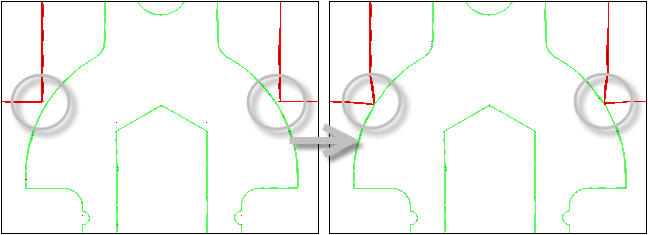
Gaps between mesh objects can be removed using the options in the Remove Gaps dialog box. The gaps can be between surfaces (face-face) or between a surface and an edge (face-edge).
Right click on the object in the Outline View. Select > from the context sensitive menu.
Select Remove Gaps Between Objects in the Operation list.
Specify an appropriate value for the Min. Gap Distance, Max. Gap Distance, and Percentage Margin.
Specify an appropriate value for Critical Angle. The critical angle is the maximum angle between the faces constituting the gap to be removed.
Ignore Orientation is enabled by default. If the thickness of any of the object selected is less than the Max. Gap Distance, then you can disable Ignore Orientation. In this case the orientations of the normals will be considered. Ensure that, the normals in the gaps to be removed are appropriately oriented (Figure 7.24: Orientation of Normals in Gap).
Select the appropriate option for feature edge extraction (none, feature, or all) and specify the Extract Angle to be used.
Select the type of gap in the Gap Type list (Face-Face or Edge-Face).
For face-face gap removal, select the appropriate option for projection in the Order list. You can choose to project the faces to the object of higher priority (Low To High Priority) or to the object of lower priority (High to Low Priority).
Click to see the faces marked for projection.
Click to remove the gaps between the objects selected.
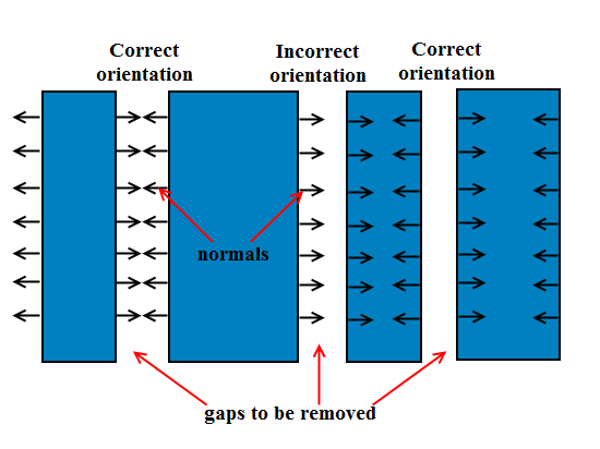
Figure 7.25: Removing Gaps Between Objects—Face-Face Option shows an example where a face-face gap between mesh objects has been removed.
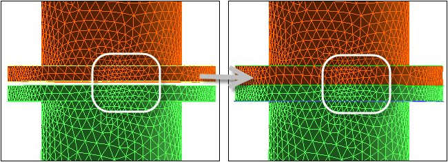
Figure 7.26: Removing Gaps Between Objects—Face-Edge Option shows an example where a face-edge gap between mesh objects has been removed.
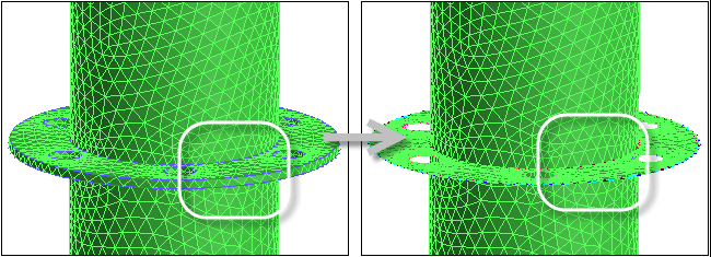
The thickness across a mesh object can be removed by projecting the close surfaces to a mid-surface. During the thickness removal operation, the object face zones will be separated in order to project the close surfaces to the mid-surface and the separated zones will be merged back after the projection. The options for thickness removal are available in the Remove Gaps dialog box.
Configurations can be distinguished as gaps or thicknesses based on the orientation of the normals on the mesh object (Figure 7.27: Gap and Thickness Configurations). The normals across a gap configuration point toward each other, while for a thickness configuration, the normals point away from each other.
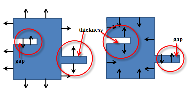
When using the option for thickness removal, ensure that the object normals are appropriately oriented depending on the configurations to be removed (see Figure 7.27: Gap and Thickness Configurations).
The generic procedure for removing thickness in objects using the Remove Gaps dialog box is as follows:
Right click on the object in the Outline View. Select > from the context sensitive menu.
Select Remove Thickness In Objects in the Operation list.
Specify an appropriate value for the Max. Gap Distance and Percentage Margin.
Specify an appropriate value for Critical Angle. The critical angle is the maximum angle between the faces constituting the thickness to be removed.
Select the appropriate option for feature edge extraction (none, feature, or all) and specify the Extract Angle to be used.
Click to remove the thickness in the objects selected.
Note: The thickness removal operation involves separation and merging back of face zones, which may affect the mesh quality. It is recommended that you save the mesh before proceeding.
Figure 7.28: Removing Thickness in Objects shows an example where the thickness in the mesh object has been removed.
The sewing operation is a face connecting operation applicable to mesh objects. Disconnected assemblies can be connected to create the conformal, triangular surface mesh on the specified objects. This operation creates conformal mesh between bodies and produces a topology-verified model. Normals are also reoriented suitably for further prism meshing.
The procedure to Sew objects is:
Select the mesh objects in the Outline View. Right-click and select > from the context sensitive menu.
Ensure that the mesh objects for the sew operation are selected in the Objects list in the Sew dialog box.
Specify the name for the mesh object to be created for the selected mesh objects.
If desired, disable the Improve option.
If disabled, you may need to improve the surface mesh quality of the mesh object created using the options in the Diagnostic Tools dialog box and the Improve dialog box.
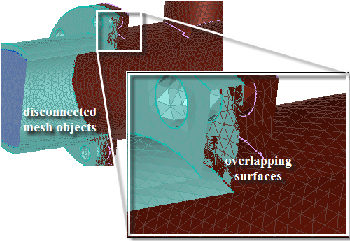
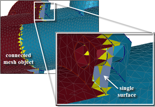
Figure 7.29: Mesh Objects to be Connected shows an example with disconnected mesh objects. The sewing operation creates the conformal surface mesh by connecting the individual objects into a single mesh object (Figure 7.30: Mesh Object Created by Sewing).
A face zone group is automatically created for the mesh object created by the Sew operation. This face zone group is prefixed by _mesh_group, and enables easy selection of mesh object face zones for various operations (improve, smooth, and so on).
Note: The sew operation is not needed for a single mesh object, or flow volume (only) extraction type problems. You can use the options in the Diagnostic Tools dialog box and then use the Improve dialog box or the command /objects/improve-object-quality to improve the surface mesh (see Improving the Mesh Objects).
You can use the command /objects/sew/sew to connect the mesh objects. Specify the objects to be connected and the name for the mesh object to be created.
Surfaces in close proximity constitute thin regions in the mesh. Examples of thin regions include sharp corners, trailing edge configurations, and so on, which may not be recovered accurately enough during the sewing operation and surface elements may span between nodes on the proximal surfaces.
You can use the command /objects/sew/set/include-thin-cut-edges-and-faces to allow better recovery of such configurations during the sewing operation.
In cases containing baffles, when the shrink-wrap method is used for the object wrapping operation, the mesh object is created with nearly overlapping surfaces representing the baffle. Though the surfaces are nearly overlapping, there is a numerically a small angle between them (parallel face angle). Such configurations constitute slits in the mesh object.
The command /objects/sew/set/process-slits-as-baffles? enables you to collapse the nearly overlapping surfaces corresponding to the baffle when the sew operation is performed to create the mesh object. Specify the maximum slit thickness relative to the minimum size specified and the parallel face angle between the faces comprising the slit when process-slits-as-baffles is enabled.
Note: When process-slits-as-baffles is enabled for the Sew operation, it is recommended that you check the mesh object created for voids or pockets. Use the command /objects/merge-voids to remove any voids or pockets created in the mesh object (see Removing Voids for details).