The previous sections describe the various meshing controls that are available to you. The following sections focuses on which controls are appropriate for free meshing, and which are appropriate for mapped meshing.
In free meshing operations, no special requirements restrict the solid model. Any model geometry, even if it is irregular, can be meshed.
The element shapes used will depend on whether you are meshing areas or volumes. For area meshing, a free mesh can consist of only quadrilateral elements, only triangular elements, or a mixture of the two. For volume meshing, a free mesh is usually restricted to tetrahedral elements. Pyramid-shaped elements may also be introduced into the tetrahedral mesh for transitioning purposes. (See Creating Transitional Pyramid Elements for information about pyramid-shaped elements.)
If your chosen element type is strictly triangular or tetrahedral, the program will use only that shape during meshing. However, if the chosen element type allows more than one shape (for example, PLANE183 or SOLID186), you can specify which shape (or shapes) to use by issuing the MSHAPE command.
You must also specify that free meshing should be used to mesh the model by issuing the MSHKEY,0 command.
For area elements that support more than one shape, a mixed shape mesh (which is usually quad-dominant) will be produced by default. An all-triangle mesh can be requested (MSHAPE,1,2D and MSHKEY,0), but is not recommended if lower-order elements are being used.
Note: There may be times when it is important to you to have an all-quadrilateral mesh. Free meshing of an area results in an all-quadrilateral mesh when the total number of line divisions on the boundaries of the area is even, and the quality of the quadrilateral elements produces no errors. You can increase the chances that the area's boundaries will have an even total number of line divisions by turning SmartSizing on and letting it determine the appropriate element divisions (rather than setting the number of element divisions on any of the boundaries manually (LESIZE)). You should also make sure that quadrilateral splitting is off (MOPT,SPLIT,OFF) to keep the program from splitting poorly shaped quadrilateral elements into triangles. (Quadrilateral splitting is turned on for error elements by default. See the description of the MOPT command for details.)
To achieve a free volume mesh, you should choose an element type that allows only a tetrahedral shape, or use an element that supports multiple shapes and set the shape option to tetrahedral only (MSHAPE,1,3D and MSHKEY,0).
For free meshing operations, element sizes are produced based on the current settings of the DESIZE command, along with ESIZE, KESIZE, and LESIZE. If SmartSizing is turned on, the element sizes will be determined by the SMRTSIZE command along with ESIZE, KESIZE, and LESIZE. (SmartSizing is recommended for free meshing.)
A special type of free meshing, called fan type meshing, is available for certain contact analysis cases that involve the meshing of 3-sided areas with the TARGE170 element. When two of the three sides have only one element division, and the third side has any number of divisions, the result will be a fan type mesh. (The LESIZE command is used to set element divisions.) Fan type meshing ensures that the program uses the minimum number of triangles to fill the area, which is important for contact problems. Consider the example shown in Figure 7.17: Example of Fan Type Meshing, in which two of the sides have only one element division, while the third side has four.
Remember that to use fan type meshing, the following conditions must be satisfied:
For more information, see the Contact Technology Guide and the description of the TARGE170 element.
You can specify that the program use all quadrilateral area elements, all triangle area elements, or all hexahedral (brick) volume elements to generate a mapped mesh. Mapped meshing requires that an area or volume be "regular", that is, it must meet certain criteria.
For mapped meshing, element sizes are produced based on the current settings of DESIZE, along with ESIZE, KESIZE, LESIZE and AESIZE settings. SmartSizing (SMRTSIZE) cannot be used for mapped meshing.
Note: Mapped meshing is not supported when hard points are used.
An area mapped mesh consists of either all quadrilateral elements or all triangular elements.
Note: Mapped triangle meshing refers to the process in which the program takes a map-meshable area and meshes it with triangular elements, based on a pattern you specify. This type of meshing is particularly useful for analyses that involve the meshing of rigid contact elements. (See the Contact Technology Guide for details about contact analyses.)
For an area to accept a mapped mesh, the following conditions must be satisfied:
The area must be bounded by either three or four lines (with or without concatenation).
The area must have equal numbers of element divisions specified on opposite sides, or have divisions matching one of the transition mesh patterns (see Figure 7.24: Applicable Transition Patterns-Transition Mapped Quadrilateral Meshes).
If the area is bounded by three lines, the number of element divisions must be even and equal on all sides.
The meshing key must be set to mapped (MSHKEY,1). This setting results in a mapped mesh of either all quadrilateral elements or all triangle elements, depending on the current element type and/or the setting of the element shape key (MSHAPE).
If your goal is a mapped triangle mesh, you can also specify the pattern the program uses to create the mesh of triangular elements (MSHPATTERN). If you do not specify a pattern, the program chooses one for you. See the MSHPATTERN command description for an illustration of the available patterns.
Figure 7.18: Area Mapped Meshes shows a basic area mapped mesh of all quadrilateral elements, and a basic area mapped mesh of all triangular elements.
If an area is bounded by more than four lines, it cannot be map meshed. However, some of the lines can be combined or "concatenated" to reduce the total number of lines to four. Line concatenation is discussed later in this section.
A suggested alternative to using line concatenation is to use the AMAP command to map mesh an area by picking three or four corners of the area. This method internally concatenates all lines between the keypoints. (Simplified area mapped meshing is described later in this section.)
You must specify equal numbers of line divisions on opposite edges of the area (or define line divisions to match one of the transition patterns) to achieve a mapped mesh. You do not necessarily have to specify line divisions on all lines. As long as mapped meshing has been requested (MSHKEY,1), the program will transfer line divisions from one line to the opposite line, and on into adjacent areas being meshed (AMESH). The program will also produce matched line divisions from AESIZE, "soft" LESIZE, KESIZE or ESIZE specifications, when possible.
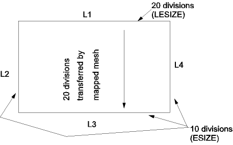
The same hierarchy that applied to LESIZE, ESIZE, etc. will also apply to transferred line divisions. Thus, in the example shown in Figure 7.19: Transferred Hard LESIZE Controls Override ESIZE Controls, LESIZE line divisions transferred from line 1 to line 3 will override explicitly defined ESIZE line divisions.
MSHKEY,1! mapped mesh
ESIZE,,10! 10 divisions set by ESIZE
LESIZE,1,,,20! 20 divisions specified for line 1
AMESH,1! 20 line divisions will be transferred onto line 3
See the MSHKEY, ESIZE, AESIZE, LESIZE, and AMESH command descriptions for more information.
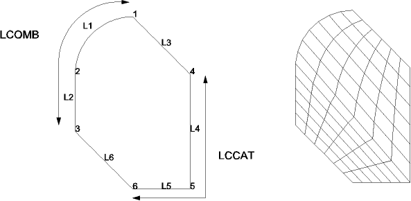
If an area is bounded by more than four lines, you can combine lines (LCOMB) or concatenate lines (LCCAT) to reduce the total number of lines to four. Whenever LCOMB is permitted (that is, when lines are tangent and are attached to the same areas), it is generally preferred over LCCAT. LCOMB can also be used for non-tangent lines, but a node will not necessarily be generated at the kink in the line.
Consider the example of Figure 7.20: Line Combination and Concatenation Can Enable Mapped Meshing, in which an area is bounded by six lines. Two of the lines can be combined, and two others concatenated, to produce an area bounded by four lines, suitable for mapped meshing.
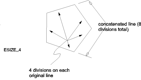
A node will be generated wherever there is a keypoint attached to a line, area, or volume. Therefore, a concatenated line will have at least as many divisions as are defined implicitly by the keypoints on that line. The program will not allow you to transfer a smaller number of divisions onto such a line. Also, if a global element size (ESIZE) is specified, it applies to your original lines, not to your concatenated lines.
Line divisions cannot be directly assigned to concatenated lines. However, divisions can be assigned to combined lines (LCOMB). Therefore, there is some advantage to using line combination instead of concatenation.
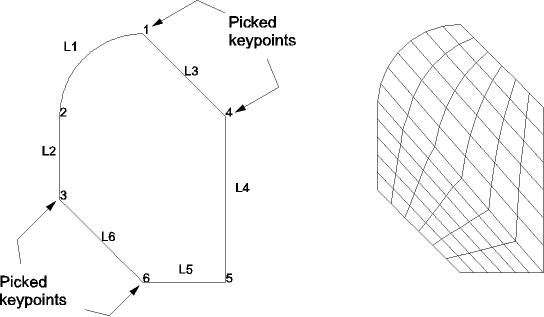
The AMAP command offers the easiest way to obtain a mapped mesh. AMAP uses specified keypoints as corners and internally concatenates all lines between the keypoints. The area is automatically meshed with all quadrilateral or all triangular elements (a MSHKEY specification is not required). The same rules about meshing controls apply for AMAP as for mapped meshing by line concatenation.
Consider the example presented earlier for concatenation, but now meshed with the AMAP method. Notice that there are multiple lines between several of the picked keypoints. After picking the area, keypoints 1, 3, 4, and 6 can be picked in any order, and the mapped mesh is automatically created.
No line concatenation is needed prior to the AMAP operation. The concatenation is done internally and then deleted. The area's line list is left unchanged.
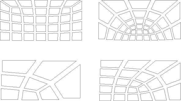
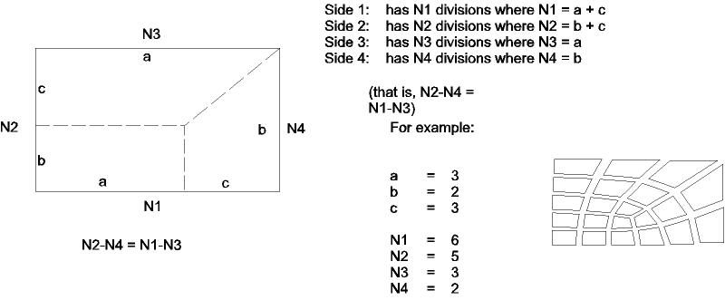
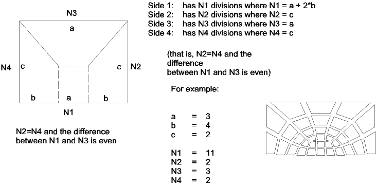
Another way to create a mapped area mesh is to specify line divisions on opposite sides of the area such that the divisions permit a transition mapped quadrilateral mesh. Transition mapped quadrilateral meshing is only applicable to four-sided areas (with or without concatenation). Some examples are shown in Figure 7.23: Examples of Transition Mapped Quadrilateral Meshes.
To achieve a transition mapped quadrilateral mesh, you must use an element type that supports a quadrilateral shape, set the meshing key to mapped (MSHKEY,1), and set the shape specification to allow quadrilaterals (MSHAPE,0,2D). (If you want a transition mapped triangle mesh, see the next section.) In addition, specified line divisions must match one of the patterns shown in Figure 7.24: Applicable Transition Patterns-Transition Mapped Quadrilateral Meshes.
The quad-dominant free mesher (MSHAPE,0 and MSHKEY,0) automatically looks for four-sided regions that match these transition patterns. If a match is found, the area is meshed with a transition mapped quadrilateral mesh, unless the resulting elements are of poor quality (in which case a free mesh will be produced).
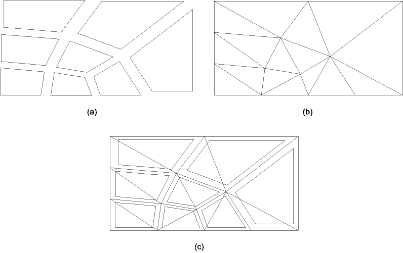
Transition mapped meshing is also valid for mapped area meshes of triangle elements. As with transition mapped quadrilateral meshing, transition mapped triangle meshing is only applicable to four-sided areas, and the specified line divisions must match one of the patterns shown in Figure 7.24: Applicable Transition Patterns-Transition Mapped Quadrilateral Meshes. To achieve a transition mapped triangle mesh, you must also use an element type that supports a triangular shape, set the meshing key to mapped (MSHKEY,1), and set the shape specification to allow triangles (MSHAPE,1,2D).
The relationship between a transition mapped quadrilateral mesh and a transition mapped triangle mesh can be seen in Figure 7.25: Mapped Meshes. Figure (b) illustrates a transition mapped triangle mesh. When you request a mapped triangle mesh, the program actually begins by map meshing the area with quadrilateral elements, and then it automatically splits the quadrilateral elements into triangles. Figure (a) shows the quadrilateral mesh that was used as the basis for the triangle mesh shown in Figure (b). Figure (c) illustrates the triangle mesh, with the quadrilateral elements superimposed over it. The dotted lines represent the boundaries of the quadrilateral elements that the program split into triangles.
To mesh a volume with all hexahedron elements, the following conditions must be satisfied:
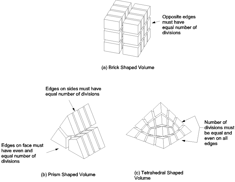
The volume must take the shape of a brick (bounded by six areas), wedge or prism (five areas), or tetrahedron (four areas).
The volume must have equal numbers of element divisions specified on opposite sides, or have divisions matching one of the transition mesh patterns for hexahedral meshes. See Figure 7.26: Examples of Element Divisions for Mapped Volume Meshing for examples of element divisions that will produce a mapped mesh for different volume shapes. Transition mesh patterns for hexahedral meshes are described later in this section.
The number of element divisions on triangular areas must be even if the volume is a prism or tetrahedron.
As with lines, you can add (AADD) or concatenate (ACCAT) areas if you need to reduce the number of areas bounding a volume for mapped meshing. If there are also lines bounding the concatenated areas, the lines must be concatenated as well. You must concatenate the areas first, then follow with line concatenations. This procedure is illustrated by the sample input listing that appears below:
! first, concatenate areas for mapped volume meshing:
ACCAT,...
! next, concatenate lines for mapped meshing of bounding areas:
LCCAT,...
LCCAT,...
VMESH,...
Note: Whenever AADD is permitted (that is, when areas are flat and coplanar), it is generally preferred over ACCAT. (Line divisions will be transferred from one edge to another as described earlier.)
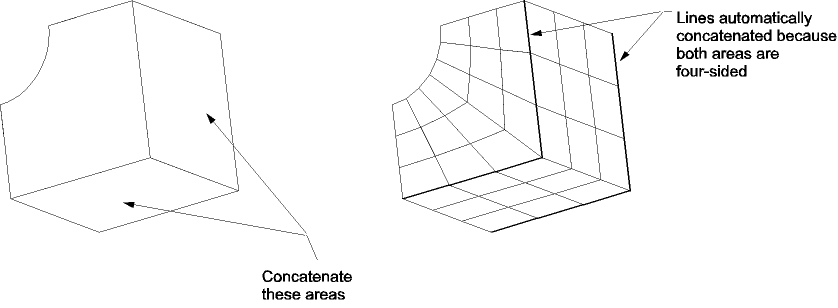
As shown in the sample input listing above, line concatenations (LCCAT) are normally required after area concatenations (ACCAT). However, if both areas that are concatenated are bounded by four lines (no concatenated lines), the line concatenation operations will be done automatically. Thus, because the areas in Figure 7.27: Area Concatenation are both bounded by four lines, line concatenation (LCCAT) is not required. Also note that deleting the concatenated area does not automatically delete the associated concatenated lines.
Area concatenation used for mapped volume meshing are shown in Figure 7.27: Area Concatenation. The lines are automatically concatenated by the area concatenation operation (ACCAT) because both areas are bounded by four lines.
See the ACCAT, LCCAT, and VMESH command descriptions for more information.
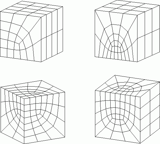
You can create a mapped volume mesh by specifying line divisions on opposite edges of the volume such that the divisions permit a transition mapped hexahedral mesh. Transition mapped hexahedral meshing is only applicable to six-sided volumes (with or without concatenation). Some examples are shown in Figure 7.28: Examples of Transition Mapped Hexahedral Meshes.
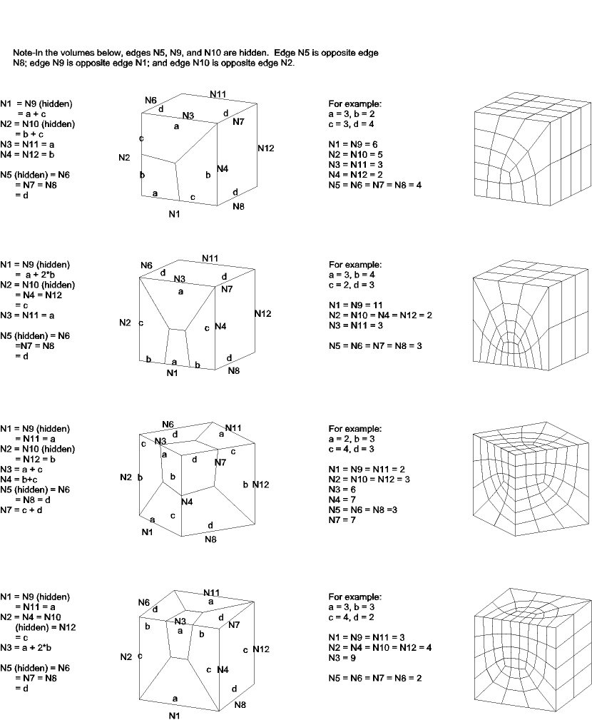
To achieve a transition mapped hexahedral mesh, you must use an element type that supports a hexahedral shape. If you previously set the element shape specification to mesh with tetrahedral-shaped elements (MSHAPE,1,3D), you must now set the shape specification to allow hexahedron (MSHAPE,0,3D). In addition, specified line divisions must match one of the patterns shown in Figure 7.29: Applicable Transition Patterns-Transition Mapped Hexahedral Meshes.
Note: Even if you specify free meshing (MSHKEY,0), the program automatically looks for six-sided volumes that match these transition patterns. If a match is found, the volume will be meshed with a transition mapped hexahedral mesh, unless the resulting elements are of poor quality (in which case the mesh will fail).
Note: As indicated in Figure 7.29: Applicable Transition Patterns-Transition Mapped Hexahedral Meshes, some of the edges of the volumes are hidden (edges N5, N9, and N10). Edge N5 is opposite edge N8, edge N9 is opposite edge N1, and edge N10 is opposite edge N2.
Concatenation is solely intended to be used as an aid to mapped meshing. It is not a Boolean "add" operation. Concatenation should be the last step you undertake before you execute a mapped mesh of your solid model, because the output entity obtained from a concatenation cannot be used in any subsequent solid modeling operation (other than meshing, clearing, or deleting). For example, a line created by an LCCAT operation cannot have any solid model loads applied to it, nor can it be part of any Boolean operation, nor can it be copied, dragged, rotated ( xGEN, xDRAG, xROTAT), etc., nor can it be used in another concatenation.
You can readily "undo" a concatenation by simply deleting the line or area produced by the concatenation:
The fastest way to delete concatenated lines or areas is by choosing menu path or .
Caution: When you use this method, the program automatically selects all concatenated lines (or areas) and deletes them without prompting you.
If you want more control over which concatenated lines or areas are selected and deleted, use either LSEL,
Type,LCCA,,,,,KSWPor ASEL,Type,ACCA,,,,,KSWP.
You can then delete all of the selected lines or areas (LDELE,ALL or ADELE,ALL) as necessary.
Although you need to be aware of the restrictions on output entities listed
earlier in this section, no such restrictions affect the input entities in a concatenation. However, the input entities
will become "lost" or "detached," so far as higher-level entities are concerned.
That is, if an area is bounded by five lines (L1-L5), and two of those lines are
concatenated (LCCAT,1,2
L6), the program will no longer recognize lines L1 and L2 as
being attached to that area. However, you can reattach L1 and L2 to the area by
deleting L6 to undo the concatenation. (See Figure 7.30: Input Lines in a Concatenation.)
Input lines in a concatenation become detached until the concatenation is undone.
If you find that concatenation becomes too restrictive for your intended modeling operations, you can usually obtain a mapped mesh by some other means, such as by subdividing an area or volume into appropriately-bounded entities. Boolean operations will often be helpful for subdividing an entity in this fashion.
See the descriptions of the ASEL, LSEL, ACCAT, LCCAT, ADELE, and LDELE commands for details.


