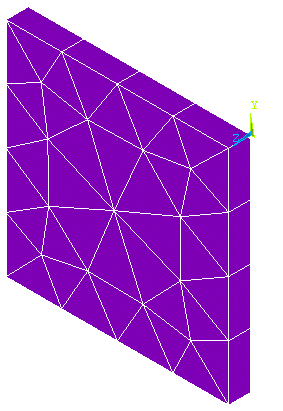
Three options are available for meshing interface elements:
There are special requirements for meshing interface elements. See Generating an Interface Mesh for Gasket Simulations in the Modeling and Meshing Guide for further details on this type of meshing.
The following example input listing shows the use of the IMESH command.
/batch,list
/title, Test to demonstrate the use of IMESH command
/com, ************************************************************
/com, *                                                          *
/com, * This is a simple test to demonstrate the use of IMESH    *
/com, * command to generate gasket elements. The model consists  *
/com, * of two blocks with gasket elements (INTER194) defined    *
/com, * between them.                                            *
/com, *                                                          *
/com, ************************************************************

/prep7

!*+++++++++++++++++++++++++++++++++++++++
!* Define Element Types
!*+++++++++++++++++++++++++++++++++++++++
et,1,187                ! Solid tetrahedral element
et,2,194	        ! Interface layer element

!*+++++++++++++++++++++++++++++++++++++++
!* Define Parameters
!*+++++++++++++++++++++++++++++++++++++++
EH=1.0
IH=0.1
DX=0
DY=0
DZ=IH
Z1=EH
Z2=Z1+IH
Z3=Z2+EH

!*+++++++++++++++++++++++++++++++++++++++
!* Generate Keypoints
!*+++++++++++++++++++++++++++++++++++++++
k,1,0,0
k,2,1,0
k,3,1,1
k,4,0,1
k,5,0,0,z1
k,6,1,0,z1
k,7,1,1,z1
k,8,0,1,z1
k,9,0,0,z2
k,10,1,0,z2
k,11,1,1,z2
k,12,0,1,z2
k,13,0,0,z3
k,14,1,0,z3
k,15,1,1,z3
k,16,0,1,z3

!*+++++++++++++++++++++++++++++++++++++++
!* Generate First Volume
!*+++++++++++++++++++++++++++++++++++++++
v,1,2,3,4,5,6,7,8

!*+++++++++++++++++++++++++++++++++++++++
!* Generate Second Volume
!*+++++++++++++++++++++++++++++++++++++++
v,9,10,11,12,13,14,15,16

!*+++++++++++++++++++++++++++++++++++++++
!* Generate Middle Volume
!*+++++++++++++++++++++++++++++++++++++++
v,5,6,7,8,9,10,11,12

!*+++++++++++++++++++++++++++++++++++++++
!* Define Element Size
!*+++++++++++++++++++++++++++++++++++++++
esize,,4	             !

!*+++++++++++++++++++++++++++++++++++++++
!* Mesh First Volume with Element Type 1
!*+++++++++++++++++++++++++++++++++++++++
type,1
mat,1
vmesh,1

!*++++++++++++++++++++++++++++++++++++++++++++
!* Generate Interface Layer with IMESH command
!* using Element Type 2 (INTER194)
!*++++++++++++++++++++++++++++++++++++++++++++
type,2
mat,2
imesh,area,6,7,0,DX,DY,DZ,TOL

!*+++++++++++++++++++++++++++++++++++++++
!* Mesh Second Volume with Element Type 1
!*+++++++++++++++++++++++++++++++++++++++
type,1
mat,1
vmesh,2

!*+++++++++++++++++++++++++++++++++++++++
!* Plot Elements
!*+++++++++++++++++++++++++++++++++++++++
/view,1  ,1,1,1
eplot
finish
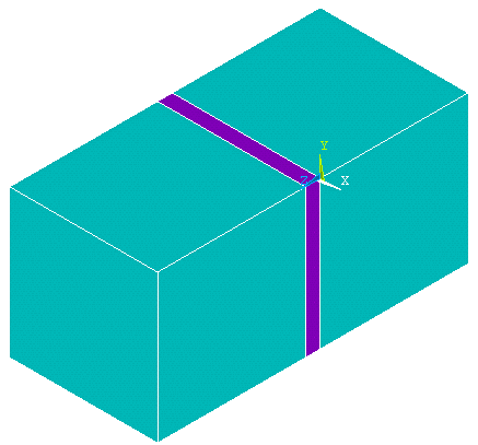
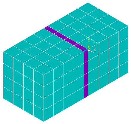
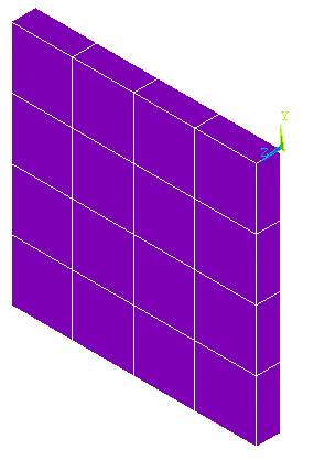
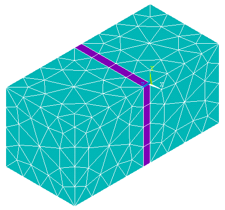
Figure 10.6: Gasket Finite Element Model Geometry shows the geometry of the finite element model, a thin interface layer between two block volumes. Figure 10.7: Whole Model Mesh with Brick Element shows the mesh with solid brick element, SOLID185, in top and bottom of block volumes, and Figure 10.8: Interface Layer Mesh shows the mesh of interface element, INTER195, in the interface layer between the two blocks. Figure 10.9: Whole Model Tetrahedral Mesh shows the mesh with solid tetrahedral element, SOLID187, in top and bottom of block volumes, and Figure 10.10: Interface Layer Mesh with Degenerated Wedge Elements shows the mesh of interface element (degenerated wedge), INTER194, in the interface layer between the two blocks.


