The eXtended Finite Element Method (XFEM) models cracks and other discontinuities by enriching the degrees of freedom in the model with additional displacement functions that account for the jump in displacements across the discontinuity. XFEM is a good engineering approach for modeling both stationary crack problems and crack-growth simulation. The method eliminates the need to remesh crack-tip regions.
The method offers the following features:
Extends the conventional finite element method to account for cracks based on the concept of partition of unity. [1][2][3][4]
Offers a way to model the cracks without explicitly meshing the crack surfaces.
Enables fracture-parameter (J-integral and stress-intensity factors) evaluation of stationary cracks in linear elastic isotropic materials. (The displacement formulation can account for the presence of singularity.)
Allows for arbitrary crack-growth within the existing mesh. No morphing or remeshing is needed.
For a growing crack, the method assumes that the discontinuities cut the element fully. (In this case, displacement formulation does not account for the presence of singularity.)
As the crack grows, the newly introduced crack segments are always assumed to have cohesive zone behavior. [2][3][4]
It is fully aligned with the crack-growth framework in Mechanical APDL.
The following topics for XFEM-based stationary crack analysis and crack-growth simulation are available:
Also see XFEM-Based Fatigue Crack-Growth, which uses singularity-based XFEM.
With the conventional finite element method (FEM), cracks are modeled explicitly as part of the geometry definition. When the crack grows (based on some fracture criterion), the mesh must be suitably updated using morphing and remeshing so that the analysis can continue.
The extended finite element method (XFEM), introduced by Belytschko and Black,[5] overcomes the requirements of updating the mesh as the crack grows. XFEM is based on the partition of unity concepts outlined in Melenk and Babuska.[1]
The techniques used in XFEM can be broadly classified into the following methods:
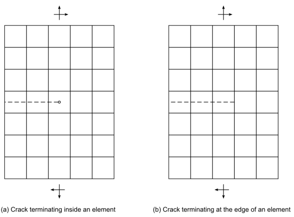
Singularity-Based Method -- Accounts for crack-tip singularities as well as the jumps in displacements across the crack surfaces. Cracks may terminate inside a finite element. (See illustration (a) in Figure 3.23: XFEM Crack Representation in a Finite Element Model.)
Phantom-Node Method -- Accounts for jumps in displacements across the crack surfaces. Crack-tip singularity is not considered. The crack terminates at the edge (or face) of a finite element. (See illustration (b) in Figure 3.23: XFEM Crack Representation in a Finite Element Model.)
In the singularity-based method, the crack is allowed to terminate inside an element. (See illustration (a) in Figure 3.23: XFEM Crack Representation in a Finite Element Model.)
The displacement functions in the FEM formulation are enhanced by introducing additional enrichment functions that capture the jump in displacement across the crack surface and also the crack-tip singularities:
where:
|
|
|
|
|
|
|
|
|
|
|
|
|
|
The functions differ according to material.[10][11][12]
The phantom-node method [3][4][8][9] considers only the displacement jump across the crack faces and ignores the crack-tip singularity contributions. Thus, the displacement formulation becomes:
By introducing phantom nodes superposed on the parent element nodes (as shown in Figure 3.24: Phantom-Node Method), the displacement function can be rewritten in terms of the displacements of the real nodes and the phantom nodes [3] as:
which leads to a superposed element formulation that essentially splits the parent element into two subelements. Here:
|
|
|
|
|
|
|
|
Only linear elastic isotropic material behavior is supported in an XFEM analysis. Element support is shown in Table 3.1: Elements Used in an XFEM Analysis.
In the finite element model, the crack is defined as a line (or surface) discontinuity in the model. Set up the initial crack as follows:
Define an enrichment region in the model associated with the crack. The enrichment region is enhanced with the additional internal nodes necessary to support the enriching displacement functions as required. Multiple initial cracks can be defined in the region.
Define the enrichment region conservatively. The analysis becomes more computational intensive as more internal nodes are added in the model.
The enriched region can be associated with a name for identification:
XFENRICH,
EnrichmentIDwhere
EnrichmentIDis the name assigned for identifying the enrichment region.
Define an element component in which the initial cracks are defined and will possibly propagate:
XFENRICH,
EnrichmentID,CompNamewhere
CompNameis the name of the element component.
The initial cracks specified in the enrichment region can be traction-free or can have an associated cohesive zone behavior if necessary. Specify a material ID that describes the cohesive zone behavior of the initial crack:
XFENRICH,
EnrichmentID,CompName,MAT_IDwhere
MAT_IDis the material ID number describing the cohesive zone behavior. If the material ID is not specified, the crack faces are assumed to be traction-free.
Specify the appropriate XFEM method:
XFENRICH,
EnrichmentID,CompName,,PHAN (default)XFENRICH,
EnrichmentID,CompName,,SINGTable 3.3: Selecting an XFEM Method
XFEM Method XFEM Analysis Supported Comments Phantom-node Crack-growth Enhancement radius (XFENRICH,,,,RADIUS) is not used. Fracture parameters J-integral (J) and stress-intensity factors (K) are not evaluated. Stationary-crack Singularity-based Stationary-crack Material ID (XFENRICH,,, MAT_ID) is not needed (as crack faces are assumed to be traction-free).
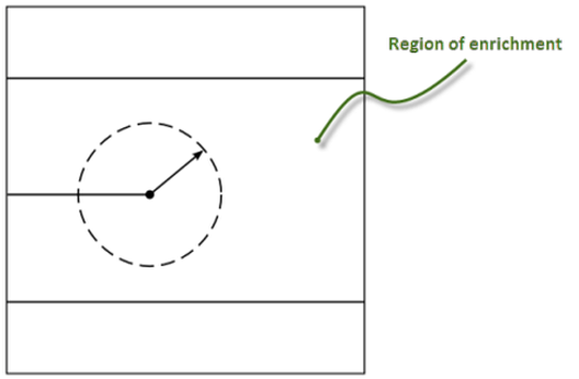
The enhancement radius applies only to the singularity-based XFEM method (XFENRICH,,,,SING).
By default, the singularity functions apply to the crack-tip element only. The crack-tip singularity does not affect the neighboring uncracked elements surrounding the crack tip.
You can account for the effects of the crack-tip singularity in a region around the crack tip by specifying a radius within which Mechanical APDL includes the singularity functions in the element formulation:
XFENRICH,
EnrichmentID,CompName,,SING,RADIUS
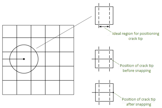
The snap-tolerance specification applies only to the 2D singularity-based XFEM method (XFENRICH,,,,SING).
In a typical singularity-based XFEM analysis, it is good practice to position the crack tip somewhere in the middle region of the element. A snap tolerance is available, enabling the crack tip to automatically snap the crack tip to the closest element edge (or face) available:
XFENRICH,
EnrichmentID,CompName,,SING,RADIUS,SNAPTOLER
Mechanical APDL considers the tolerance value and the average element length to determine if the crack tip should be snapped to the face or not. The default snap tolerance is 1.E-6.
The following two methods are available for defining the initial crack:
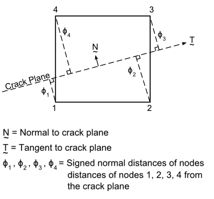
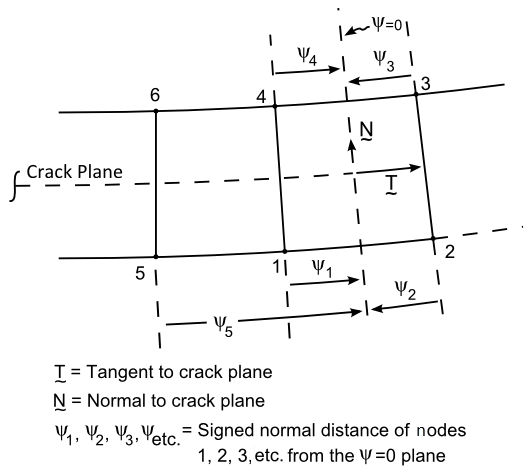
The level-set method defines the location of the crack in the finite element model.[13][14] The crack geometry in an element is defined by specifying two signed distance functions at the nodes of the element. The two signed distance functions at the nodes represent the position of the nodes from the crack surface and from the crack front.
Define the level-set values PHI and
PSI:
XFDATA,
LSM,ELEMNUM,NODENUM,PHI,PSI
The level-set value PHI is evaluated as shown
in the following figure:
The value of PHI must be > 0 or < 0.
(PHI = 0 is invalid.)
The level-set value PSI is evaluated for all
cracked elements associated with a given crack tip, as shown:
The PSI = 0 plane is assumed to be
perpendicular to the crack plane at the crack tip.
Table 3.4: Considerations for Defining the Initial Crack
| Criterion | Comments |
|---|---|
| Crack-tip position | For the singularity-based method, the crack tip can be positioned anywhere within or on the edge (or face) of the element. For the phantom-node method, the crack tip must be positioned on the edge (or face) of the element (that is, the crack cuts the element fully). |
| PSI value | Not used with the phantom-node method. |
| Multiple cracks | If you define multiple cracks in the model, the
PHI and
PSI values must be associated
with the appropriate cracks. |
| Initial crack position | The initial crack cannot cut the element at the nodes of
the element nor pass through the nodes of an element. If the
crack is very close to an edge (or face), position it
slightly away from the edge (or face) of an element by
specifying a suitable PHI
value. |
With this method, the crack-surface geometry is positioned appropriately within the base-element mesh, then discretized using MESH200 elements.
Mechanical APDL calculates the signed distance functions ϕ and ψ at the nodes of the cracked elements. You can list the ϕ and ψ values of the cracked elements (XFLIST).
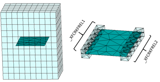
Mechanical APDL identifies and stores crack-front elements in an element
component named _XFCRKFREL
n (where n = 1, 2, 3,
… depending on the number of crack fronts arbitrarily identified in
the model). For example, if a model has two crack fronts, the two
crack-front element components are identified as: _XFCRKFREL1 and
_XFCRKFREL2.
The component name and the list of elements in the component appear in the output file for verification. You can also use the component to identify the crack-front elements required for the fracture parameter calculations (CINT,CXFE).
Defining the Crack Surface for an XFEM Analysis Using MESH200 Elements
Define the base finite element mesh for the model (composed of either PLANE182 [for 2D] or SOLID185 [for 3D] elements).
Identify the location of the crack surface in the base mesh and insert the geometry of the crack surface within the base finite element mesh.
Ensure that the crack geometry does not intersect the base mesh at the nodes of the elements.
Discretize the crack-surface geometry with MESH200 elements:
For 2D: Use 2D lines defined by two nodes and set KEYOPT(1) = 0.
For 3D: Use 3D triangles defined by three nodes and set KEYOPT(1) = 4.
Set up an element component composed of the MESH200 elements used to define the crack surface(s).
Set up a node component composed of the crack-front nodes of the MESH200 elements.
Calculate the signed distance functions of the nodes of the intersected base mesh elements:
XFCRKMESH,
EnrichId,Mesh200Comp,CrackFrontNodeComp
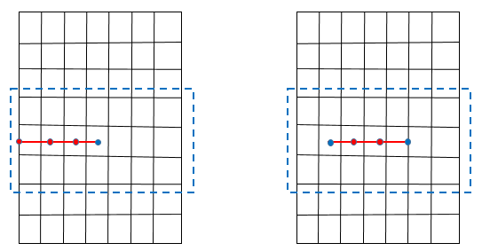
This figure shows edge-crack and center-crack specimens:
The blue box identifies the previously defined (XFENRICH) base-element component. The red line indicates the crack surface meshed with MESH200 elements (grouped as an element component). Blue dots indicate crack-tip nodes (grouped into a node component).
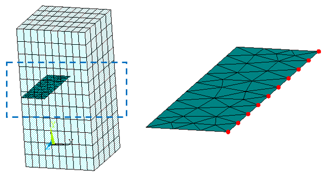
This figure shows an edge-crack specimen, the crack surface discretized with MESH200 elements:
The blue box identifies the previously defined (XFENRICH) base-element component. The MESH200 elements are grouped as an element component. Red dots indicate crack-front nodes (grouped into a node component) on the crack-surface mesh.
This figure shows how Mechanical APDL identifies crack-front elements for a center crack, given a properly defined crack surface:
Both the crack-front elements and the MESH200 elements are shown for clarity.
Example 3.15: Generating a Center Crack in a 2D XFEM Model (MESH200 Method)
/prep7
/com
/com ******************************************************
/com
/com    Sample input file for generating a center crack
/com    in a 2D XFEM model
/com
/com ******************************************************

! element types
et,1,182

!materials
mp, ex,   1, 3.0e6
mp, nuxy,  1, 0.3
mp, dens, 1, 1.0

! define rectangular area
blc4, 0.0, 0.0, 8, 10, 0

! mesh the area
type, 1
mat, 1
lesize, 1 , , , 11
lesize, 2 , , , 11
mshkey,1
amesh, 1

! Element component for XFENRICH command
esel,s,cent,x,0, 8
esel,r,cent,y,4,6
cm, testcmp, elem
allsel

! define keypoints for crack surface
k, 11, 2.0, 5.0
k, 12, 6.2, 5.0
l, 11,12

! mesh the crack surface with MESH200 elements
et, 2, 200, 0 ! keyopt(1) = 0 to generate line meshes
type,2
mat, 2
lmesh,5

! define Mesh200 element component defining the crack surface
esel,s,type,,2
cm,m200el,elem
allsel

! mesh200 node component for crk front
nsel,s,loc,x,2.0
nsel,r,loc,y,5.0
nsel,a,loc,x,6.2
nsel,r,loc,y,5.0
cm, m200nd, node
allsel

!define enrichment identification
xfenrich, ENRICH1, TESTCMP,,SING,0

! define LSM values
xfcrkmesh,ENRICH1, m200el, m200nd
allsel

xflist  ! print crack information
Example 3.16: Generating a Center Crack in a 3D XFEM Model (MESH200 Method)
/prep7
/com
/com ******************************************************
/com
/com    Sample input file for generating a center crack
/com    in a 3D XFEM model
/com
/com ******************************************************

! element types
et,1,185

!material definition
mp, ex,   1, 3.0e6
mp, nuxy,  1, 0.3
mp, dens, 1, 1.0

! define rectangular block
blc4, 0.0, 0.0, 8, 10, 5

! mesh the volume
type, 1
mat, 1
lesize, 1 , , , 11
lesize, 2 , , , 10
lesize, 11, , , 5
vmesh, 1

! Element component for XFENRICH command
esel,s,cent,x,0, 8
esel,r,cent,y,4,6
cm, testcmp, elem
allsel

! define keypoints for crack surface
k, 11, 2.0, 5.0, 5.0
k, 12, 6.2, 5.0, 5.0
k, 13, 6.2, 5.0, 0.0
k, 14, 2.0, 5.0, 0.0
a, 11,12,13,14

! mesh the crack surface with MESH200 elements
et, 2, 200, 4 ! keyopt(1) = 4 to generate triangular meshes
type,2
mat, 2
amesh,7

! define Mesh200 element component defining the crack surface
esel,s,type,,2
cm,m200el,elem
allsel

! mesh200 node component for crk front
lsel, s, line,,14
lsel, a, line,,16
nsll,,1
cm, m200nd, node
allsel

!define enrichment identification
xfenrich, ENRICH1, TESTCMP,,SING,0

! define LSM values
xfcrkmesh,ENRICH1, m200el, m200nd
allsel

xflist ! print crack informationThe XFEM method for stationary cracks applies to the singularity-based method only, as that method enables evaluation of the J-integral and stress-intensity factors (SIFS) parameters.
Although the phantom-node XFEM method can be used for stationary-crack analysis, J-integral and SIFS fracture parameters cannot be evaluated when using this method.
The following topics are available:
For a stationary crack analysis, Ansys, Inc. recommends using the singularity-based method XFEM method. This approach accounts for both crack-tip singularity effects and the jumps in displacements across the crack surfaces. Cracks may terminate at the edge (or face) of a finite element or they may terminate inside the element.
The displacement function in the singularity-based method is:
The singularity functions are given as:[5][10]
Where represent the coordinates of a polar coordinate system with
the origin centered at the crack tip.
The level-set values offer a convenient way of characterizing the crack-tip stress
and displacement fields instead of the local
coordinates.
The relationship is expressed as:[14]
and
All the expressions in the finite element discretization of the virtual work
is expressed in terms of .
After the model is set up, standard solution procedure apply. You can request the fracture parameters J-integral and stress-intensity factors (CINT).
The commands for requesting the fracture parameters are:
| Command | Purpose |
|---|---|
| CINT,NEW,1 | Requests a new domain integral calculation |
| CINT,TYPE,JINT (or SIFS) | Requests the desired fracture parameter (J-integral or stress-intensity factors, respectively). |
CINT,CXFE,CompName
| Specifies the name of element component
(CompName) containing the
crack-front element set. |
CINT,NCON,n
| Specifies the number of contours
(n) required. |
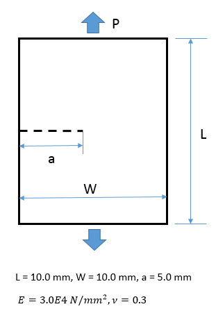
The XFEM-based stationary crack simulation uses a single edge notched (SEN) specimen with a crack-length (a) to -width (W) ratio, a/W = 0.5. The specimen is subjected to pressure P = 100 N/mm2 on the upper and lower faces.
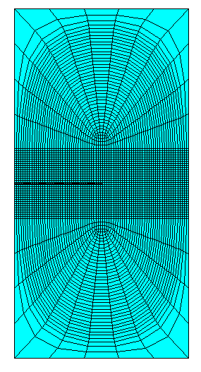
The specimen is modeled with the PLANE182 element (with KEYOPT(1) = 0, KEYOPT(3) =2, KEYOPT(6) = 0). A fine mesh is used in the region near the crack surface:
Linear elastic isotropic material behavior is assumed.
The fracture parameter and
are calculated and stored (CINT) for every
substep of the analysis. During the post-processing stage, the
and
values are extracted (PRCINT).
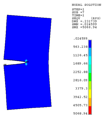
This table compares the calculated values of the J-integral and stress-intensity factors (averaged over contours 3 through 8) to the theoretical results:
Table 3.5: Calculated Results vs. Theoretical Results
| Fracture Parameter | Mechanical APDL Results | Theoretical Results |
|---|---|---|
|
| 1127.3 | 1120.383 |
|
| 38.517 | 38.076 |
Following is the input file used for the stationary crack analysis of the SEN specimen:
/prep7

! used to create a cdb file if needed
_geomgen=1
_exit=0

*if,_geomgen,eq,1,then

a=5           !--- CRACK LENGTH
W=10          !--- WIDTH OF MODEL
H=20          !--- HEIGHT OF MODEL
PRES=100      !--- PRESSURE
E=3.0e4       !--- YOUNG'S MODULUS
NU=0.3        !--- POISSON'S RATIO
RO=1.0        !--- DENSITY

! element types etc
et,1,182
keyopt,1,3,2

! continuum material behavior
mp, ex,   1, 3.e04
mp, nuxy,  1, 0.3
mp, dens, 1, 1.

! define keypoints
k, 1,  0.0, -2.0
k, 2,  W, -2.0
k, 3,  W, 2.0
k, 4,  0.0, 2.0

k, 5,  W,   -H/2
k, 6,  0.0, -H/2

k, 7,  0.0,  H/2
k, 8,  W,    H/2

! define area with KP
a, 1,2,3,4
a, 1,2,5,6
a, 3,4,7,8

! set up the meshing size
xnume=79    ! number of elements in x,  which should be odd
ynume=33    ! number of elements in y , which should be odd
lsel,s,line,,1,3,2
LESIZE,all, , ,xnume, , , , ,1
lsel,s,line,,2,4,2
LESIZE,all, , ,ynume, , , , ,1


! mesh the area
type, 1
mat, 1
MSHKEY,1
amesh,1
esize,10/5
MSHKEY,0
amesh,2,3
allsel


! Element component required for XFENRICH command
esel, s, cent, y, -2,2
esel, r, cent, x,  0,9
cm, testcmp, elem
allsel

!
! define enrichment identification
!
xfenrich, ENRICH1, testcmp, , SING,1.5
allsel

/com *************************************************************
/com
/com                    INITIAL CRACK DATA
/com
/com *************************************************************

yc = 0.0
xc = 5.0
nsel, s, loc, x,   0  , xc
esln,s,
esel, r, cent, y, -1e-3, 1e-3

cm, cenelem, elem
nelem = 1000
iel = 0
Phi = 0.0
Psi = 0.0
*do, i, 1, nelem, 1
 iel = elnext(iel)
 *if, iel, ne, 0, then
  *do, j, 1, 4, 1
    nd = nelem(iel,j)
    Phi = ny(nd) - yc
    Psi = nx(nd) - xc
    xfdata, ENRICH1, LSM, iel, nd, Phi, Psi
  *enddo
 *endif
*enddo

xflist
! crk tip element
esel,s,cent,x,xc-10/xnume/2,xc+10/xnume/2
esel,r,cent,y,-1e-2,1e-2

cm, crktipelem, elem
allsel,all

!b.c. - bottom face
nsel, s, loc, y, -10.0
sf, all, pres, -100
allsel

! b.c. - top face
nsel, s, loc, y, 10.0
sf, all, pres, -100
allsel

! b.c - fix rbm - nodes on rt face
nsel, s, loc, x, 10.0
nsel, r, loc, y, -4/ynume/2*1.05,4/ynume/2*1.05
d, all, all, 0.
allsel

cdwrite,all,xfem-sl201s,cdb

*if,_exit,eq,1,then
   /exit,nosave
*endif

*else

/PREP7
   cdread,db,xfem-sl201s,cdb
*endif
finish


! Solution Module

/solu
antype,0
time, 1.0
deltim, 0.1, 1.0E-01, 0.2
outres,all, all

 ! CINT calculations
CINT, NEW, 1
CINT, TYPE, JINT
CINT, CXFE, crktipelem
CINT, NCON, 8
CINT, NORM, 0, 2

CINT, NEW, 2
CINT, TYPE, SIFS
CINT, CXFE, crktipelem
CINT, NCON, 8
CINT, NORM, 0, 2
solve
finish

/post1

set,last,last

/OUT
/COM ***** RESULTS  *****
/COM
/COM ***** PRINT NODAL RESULTS *****
/COM
/COM >>> JINTEGRAL
/COM
PRCINT,1,,JINT
/COM
/COM >>> MODE 1 STRESS INTENSITY FACTOR
/COM
PRCINT,2,,K1
/COM
/COM >>> MODE 2 STRESS INTENSITY FACTOR
/COM
PRCINT,2,,K2
/COM

/COM
/COM
/com, expected results J = 38.076167163718
/com, expected results KI = 1120.3830854420
/com, expected results KII = 0

/exit,nosaveAn XFEM crack-growth simulation is assumed to be quasi-static. The phantom-node method is used for such simulations.
Singularity-based quasi-static crack-growth is not supported.
The following topics are available:
Following is the general process for performing an XFEM-based crack-growth simulation:
- 3.8.5.1.1. Step 1: Define an Initial Crack
- 3.8.5.1.2. Step 2: Define the Crack-Growth Criterion
- 3.8.5.1.3. Step 3: Define the Decay of Stresses on the Newly Created Crack Segments
- 3.8.5.1.4. Step 4: Specify Cohesive Zone Behavior on Initial Crack
- 3.8.5.1.5. Step 5: Perform the Crack-Growth Criterion Evaluation
- 3.8.5.1.6. Step 6: Perform the Crack-Growth Calculation
A crack-growth criterion must be specified for newly cracked cohesive segments to initiate ahead of the existing cracks. When the critical value of the crack-growth criterion is reached ahead of the crack, new cohesive segments are introduced in the elements ahead of the current crack front. The crack segments are such that they fully cut the elements ahead of the crack. The crack propagates at the rate of only one element at a time.
The following topics related to defining fine the crack-growth criterion are also available:
The available crack-growth criteria are:
STTMAX - Maximum circumferential stress criterion
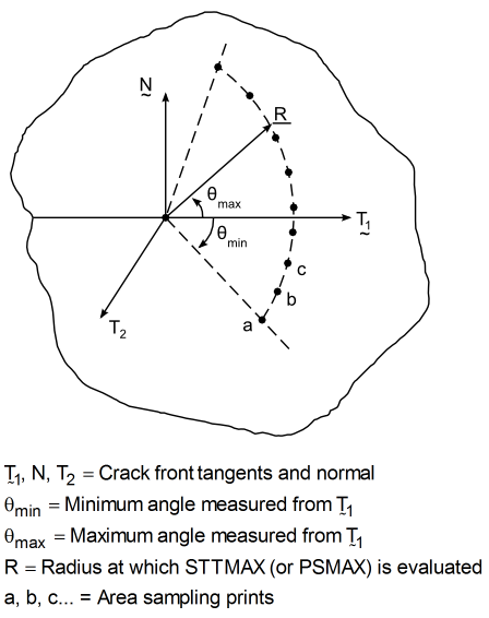
The maximum circumferential stress criterion [7] is based on evaluating the maximum value of the circumferential stress
when sweeping around the crack tip. (See Figure 3.35: Evaluation of STTMAX (or PSMAX) Around the Crack Tip.) You can specify the positions at which
is evaluated by specifying both the distance ahead of the crack tip and the angles to be scanned (CINT).
PSMAX - Circumferential stress criterion based on
An alternative to the maximum circumferential stress criterion is to evaluate the circumferential stress at a point where
. Again, the location at which
is evaluated can be specified (CINT).
Ideally, the maximum circumferential stress criterion and the circumferential stress criterion based on
yield the same result. Due to finite element discretization, however, they may yield slightly different results.
When the cohesive segments are initiated, the cohesive stresses in the crack segments gradually decrease to zero as the deformation progresses. The decay of the cohesive stresses is modeled based on a rigid linear cohesive law.[6]
To define the rigid linear law, issue the TB,CGCR,,,,RLIN command, then specify the following material constants via the TBDATA command.
Initial cracks in the model may or may not have cohesive behavior. If the initial crack requires cohesive behavior:
Issue the TB,CZM,,,,BILI command, then specify the material constants via the TBDATA command. (See Bilinear Cohesive Zone Material for Interface Elements and Contact Elements in the Material Reference.)
Specify the material ID (
MAT_IDon the XFENRICH command) to invoke the cohesive behavior on the initial crack.
XFEM supports bilinear (BILI) cohesive zone material behavior only.
By default, the interaction between the crack surfaces is taken into account using a simple penalty contact formulation in the normal direction. The contact behavior is activated only when the crack surfaces are assumed to be closed or penetrating. The crack faces are assumed to be in frictionless contact.
The default contact behavior cannot be changed.
Perform the following tasks to evaluate the maximum circumferential stress ahead of the crack front:
Define the elements that form the crack front as a crack-front element set:
CINT,CXFE,
CompNamewhere
CompNameis the name of the element component.Define the distance ahead of the crack tip (front) at which the circumferential stress is evaluated:
CINT,RADIUS,
VALUEThe default distance value (
VALUE) is twice the average element length of all elements in the element component specified via the XFENRICH command.Define the number of intervals, and the minimum and maximum values, for the sweep angle:
CINT,RSWEEP,
NUM_INTERVALS,MIN_ANGLE,MAX_ANGLEMechanical APDL uses the current crack direction as the basis to sweep around the crack tip from the minimum to the maximum at the given radius (CINT,RADIUS,
VALUE), thereby identifying locations around the crack tip at which the circumferential stress will be sampled.If this command is not issued, only the location along the current crack-extension direction at the given radius is sampled.
Calculate the circumferential stress:
CINT,TYPE,STTMAX (or PSMAX)
As the crack grows, the crack-front elements are updated internally so
that the crack advances properly. The specified component
(CINT,CXFE,CompName),
however, is not updated.
Other Action arguments on the
CINT command (such as
Action = CTNC, CENC, NCON, SYMM, UMM, or
EDIR) are not considered in an XFEM-based crack-growth analysis.
The crack-growth calculation occurs in the solution phase once the analysis has converged. The solution command CGROW defines all necessary crack-growth calculation parameters.
Perform the crack-growth calculation as follows:
Initiate the crack-growth set:
CGROW,NEW,
SET_NUMwhere
SET_NUMis the crack-growth set number.Specify the crack-calculation ID:
CGROW,CID,
ID_NUMwhere
ID_NUMis the crack-calculation ID (CINT,NEW,ID_NUM) for either of the fracture parameter calculations (STTMAX or PSMAX).Specify the XFEM crack-growth method:
CGROW,METHOD,XFEM
The initial crack must have already been specified (XFENRICH and XFDATA) for the XFEM method.
Specify the fracture criterion:
CGROW,FCOPTION,MTAB,
MAT_IDwhere
MAT_IDis the material ID number for the material table (specified via the TB,CGCR command).If this command is not issued, the crack does not propagate.
Other Action arguments on the
CGROW command (such as
Action = CPATH, DTMIN, DTMAX, or STOP ) are
not considered in an XFEM-based crack-growth analysis.
In 2D crack-growth, the crack front consists of a single node or tip, and new crack segments start from the previous crack tip.
In 3D crack-growth, however, the crack front consists of several segments, and the new crack front may not evolve as a smooth surface from the previous crack front. In such cases, Mechanical APDL attempts to compensate via an element-wise smoothing algorithm based on the technique suggested in Duan.[4]
The smoothing operation may result in the subsequent crack front being discontinuous along the crack front and with respect to the previous crack front. Generally, however, the crack front propagates in the appropriate direction depending on the applied loads and the local stress and deformation fields surrounding the crack front.
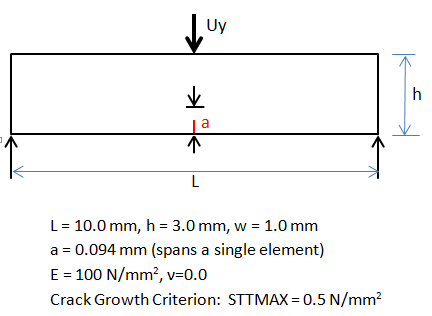
This XFEM-based crack-growth simulation example uses a three-point bending problem with an initial traction-free crack at the middle of the bottom edge of the specimen, as shown:
To propagate the crack, a displacement boundary condition is applied at the center of the top edge of the specimen.
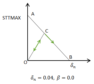
This figure shows the linear evolution of the stresses in the newly cracked segments:
As the normal displacement between the two surfaces of the cracked segment increases, the cohesive stresses in the cracked segment decreases linearly from A to B. The unloading and reloading path at any point C follows the path C-O. The value of STTMAX is taken from the crack-growth criterion specified.
The mesh near the region where the crack cuts the single element is shown in the following figure:
The crack is modeled as cutting just a single element at the edge.
The PLANE182 element (with KEYOPT(1) = 0 and KEYOPT(6) = 0) is used to model the specimen. Plane strain conditions are assumed. A fine mesh is used in the region where the crack grows, while coarse mesh is used for the rest of the specimen.
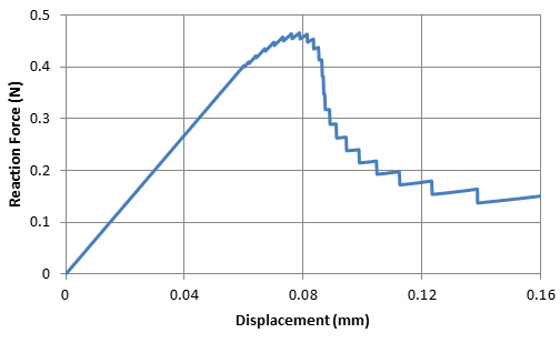
The force increases with the applied displacement and slowly peaks as the crack begins to grow. The reaction force then decreases rapidly in the initial phase of crack-growth and then slows down with subsequent crack-growth. The results are similar to the reference results.[8]
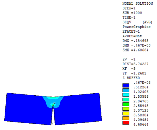
As expected, the crack propagates in the vertical direction towards the point of application of the displacement boundary condition, as shown:
Following is the input file used for the crack-growth simulation of the three-point bending specimen:
/prep7
et,1,182
keyopt,1,3,2               ! Plane strain option

!continuum material behavior
mp, ex,		1, 100.0        ! Young's Modulus
mp, nuxy,	1, 0.0          ! Poisson's Ratio
mp, dens,	1, 1.0          ! Density

!crack-growth criterion
tb, cgcr, 2, , , STTMAX    ! Fracture Behavior: Maximum circumferential stress
tbdata, 1, 0.5             ! Maximum normal traction:  = 0.5 N/mm2

!Decay of stresses on newly cracked interface
tb, cgcr, 2, , , RLIN
tbdata, 1, 0.04, , 0.0

! Define nodes and areas
k, 1, 0.0,  0.0
k, 2, 4.0,  0.0
k, 3, 4.0,  3.0
k, 4, 0.0,  3.0
k, 5, 6.0,  0.0
k, 6, 6.0,  3.0
k, 7, 10.0, 0.0
k, 8, 10.0, 3.0

a, 1,2,3,4                ! Area #1
a, 2,5,6,3                ! Area #2
a, 5,7,8,6                ! Area #3

! Mesh areas
type,1
mat, 1
esize,2.0/21              ! Element size
amesh,2                   ! Mesh area #2

esize,0.4
amesh,1,3,2	               ! Mesh areas #1 & #3


! Element component required for XFENRICH command
esel,s,cent,x,4.0,6.0
cm, testcmp, elem
allsel

! Define enrichment identification
xfenrich,ENRICH1,TESTCMP  ! Defines parameters associated with crack propagation using XFEM
xfdata, ENRICH1, LSM, 11,  12,  4.76190E-02
xfdata, ENRICH1, LSM, 11,  13, -4.76190E-02
xfdata, ENRICH1, LSM, 11, 417, -4.76190E-02
xfdata, ENRICH1, LSM, 11, 386,  4.76190E-02

/com ******************************************
/com        LISTING OF CRACK INFORMATION
/com ******************************************

xflist

! Crack-tip element
esel,s,elem,,11
cm, crktipelem, elem      ! Element set component for CINT command
allsel,all

! B.C. Left corner node
nsel,s,loc, x, 0.0
nsel,r,loc, y, 0.0
d, all, uy,0.0
allsel

! B.C. Right corner node
nsel,s,loc, x, 10.0
nsel,r,loc, y, 0.0
d, all, uy,0.0
allsel

! Loading - Displacement on two nodes on top
nsel,s,loc, x, 4.95, 5.048
nsel,r,loc, y, 3.0
d, all, uy, -0.16         ! Uy = -0.16mm
d, all, ux, 0
allsel

finish

/SOLU
antype,0
time, 1.0
deltim, 0.001, 1.E-06, 0.001
outres,all, all

! CINT calculations : Defines parameters associated with fracture parameter calculations
CINT, NEW, 1
CINT, CXFE, crktipelem    ! Crack-tip element
CINT, TYPE, STTMAX        ! Uses STTMAX
CINT, RSWEEP, 181, -90, 90

! CGROW calculations : Defines crack-growth information
CGROW, NEW, 1
CGROW, CID, 1
CGROW, METHOD, XFEM       ! Uses XFEM method for the crack propagation
CGROW, FCOPTION, MTAB, 2  ! Fracture criterion

SOLVE


/com *************************************************************
/com
/com                    CRACK DATA AFTER PROPAGATION
/com
/com *************************************************************
xflist
finish

/post1
set,list
set,last,last
*get,ldstep, active, 0, set, lstp        ! current ldstep #
*get,nsubst, active, 0, set, nset,last   ! # of data sets on results file
*dim,nd,array,2
nd(1) = 65
nd(2)= 66
*dim,u,table,nsubst
*dim,f,table,nsubst
*dim,t,table,nsubst
*do, j, 1, nsubst
   set,1,j
   *get,dispY,node,nd(1),u,y
   u(j) = -dispY
   *get,curtim,active,0,set,time
   t(j) = curtim
   totforce = 0.0D0
   *do, i, 1, 2
      *get,nfor, node, nd(i), RF, FY
       totforce = totforce - nfor        ! reaction
   *enddo
   f(j) = totforce
*enddo

/COM *************************************************
/COM
/COM             TIME vs. REACTION FORCE
/COM
/COM *************************************************

*vwrite,u(1), f(1)
(1x,'  ', f10.4, '  ', F10.4)
finishThese assumptions and restrictions apply to XFEM-based crack-growth simulation:
Material behavior is assumed to be linearly elastic. The available fracture criteria are valid only for cracks in homogeneous linear elastic materials.
The analysis is assumed to be quasi-static. Other analysis types are not available.
Because the crack-tip singularity effects are not incorporated into the analysis, the stress and deformation fields around the crack tip are only approximate. This assumption may result in approximate crack direction prediction during subsequent crack-growth. Crack direction prediction may also be affected by boundaries, other discontinuities, and the local stress and deformation fields due to discretization.
The crack-propagation direction depends on the distance ahead of the crack tip (front) at which the circumferential stress is evaluated. Some experimentation may be required in when specifying the radius value (CINT,RADIUS,
VALUE).Pressure loads on faces of cracked elements are ignored. If the element is not cracked, pressure loads are imposed; however, if the element cracks during deformation, Mechanical APDL ceases pressure load application.
In a 3D XFEM-based analysis, avoid using degenerate forms of the SOLID185 element (prisms, tetrahedron and pyramids) in the region where the initial crack is defined or assumed to grow.
A fracture criterion is evaluated after the substep is converged and has completed. If the time stepping is large, the fracture criterion ratio (CGROW,FCRAT,
VALUE) may be exceeded. Limiting the incremental time step for the substeps results in a better approximation to the fracture criterion ratio.Contact elements are not used in regions where the crack is defined or is assumed to grow.
Element birth and death is not supported.
Distributed-memory parallel processing is not supported.
Use the following standard POST1 (/POST1) commands for postprocessing XFEM-based analysis results:
| Command | Purpose |
|---|---|
| ANDATA | Displays animated graphics data for nonlinear problems |
| ANTIME | Generates a sequential contour animation over a range of time |
| *GET | Retrieves a value and stores it as a scalar parameter or part of an array parameter |
| PLCKSURF | Plots the PHI = 0 level set surface in an XFEM-based crack analysis |
| PLDISP | Displays the displaced structure |
| PLESOL | Displays the solution results as discontinuous element contours |
| PLNSOL | Displays results as continuous contours |
| PLVECT | Displays results as vectors |
| PRCINT | Prints fracture parameters and crack-growth information |
| PRESOL | Prints element solution results |
| PRNSOL | Prints nodal solution results |
| PRVECT | Prints results as vector magnitude and direction cosines |
To visualize the cracked elements in postprocessing, write the element miscellaneous data to the results file (OUTRES, MISC).
The POST26 time-history postprocessor (/POST26) is not supported for XFEM analysis.
The full-display option (/GRAPHICS,FULL) for model geometry and results is not available for XFEM analysis.
A considerable body of literature exists concerning crack-growth simulation with XFEM. The references used here are by no means exhaustive.
Melenk, J. and I. Babuska. “The Partition of Unity Finite Element Method: Basic Theory and Applications.” Computer Methods in Applied Mechanics and Engineering. 39: 289-314 (1996).
Remmers, J.J.C. R. de Borst, and A. Needleman. “The Simulation of Dynamic Crack Propagation using the Cohesive Segments Method.” Journal of the Mechanics and Physics of Solids. 56: 70-92 (2008).
Song, J. H., P. M. A. Areias, and T. Belytschko. “A Method for Dynamic Crack and Shear Band Propagation with Phantom Nodes.” International Journal for Numerical Methods in Engineering. 67: 868-893 (2006).
Duan, Qingling., and Jeong-Hoon Song, Thomas Menouillard, and Ted Belytschko. “Element-local Level-Set Method for Three-Dimensional Dynamic Crack-Growth.” International Journal for Numerical Methods in Engineering. 80: 1520-1543 (2009).
Belytschko, T. and T. Black. “Elastic Crack-Growth in Finite Elements with Minimal Remeshing.” International Journal for Numerical Methods in Engineering. 45: 601-620 (1999).
Ortiz, M. and A. Pandolfi. “Finite-Deformation Irreversible Cohesive Elements for Three-Dimensional Crack-Propagation Analysis.” International Journal for Numerical Methods in Engineering. 44: 1267-1282 (1999).
Erdogan, F. and G. C. Sih. “On the Crack Extension in Plates under Plane Loading and Transverse Shear.” ASME Journal of Basic Engineering. 85: 519-527 (1963).
Mergheim, J. E. Kuhl, and P. Steinmann. “A Finite Element Method for the Computational Modeling of Cohesive Cracks.” International Journal For Numerical Methods in Engineering. 63: 276-289 (2005).
Hansbo, A. and P. Hansbo. “A Finite Element Method for the Simulation of Strong and Weak discontinuities in Elasticity.” Computer Methods in Applied Mechanics and Engineering. 191: 3523-3540 (2004).
Sukumar, N. and J.-H Prevost. “Modeling Quasi-Static Crack-Growth with Extended Finite Element Method Part I: Computer Implementation.” International Journal for Solids and Structures. 40: 7513-7537 (2003).
Sukumar, N. and Z. Y. Huang, J.-H. Prevost and Z. Suo. “Partition of Unity Enrichment for Bimaterial Interface Cracks.” International Journal for Numerical Methods in Engineering. 59: 1075-1102 (2004).
Elguedj, T. and A. Combescure. “Appropriate Extended Functions for X-FEM Simulation of Plastic Fracture Mechanics.” Computer Methods in Applied Mechanics and Engineering. 195: 501-515 (2006).
Osher, S. and J. A. Sethian. “Fronts Propagating with Curvature-Dependent Speed: Algorithms based on Hamilton-Jacobi formulations.” Journal of Computational Physics. 79: 12-49 (1988).
Stolarska, M. DL Chopp, N. Moes, T. Belytschko. “Modeling Crack-Growth by Level Sets in the Extended Finite Element Method.” International Journal for Numerical Methods in Engineering. 51: 943-960 (2001).
Sethian, J. "A Marching Level-Set Method For Monotonically Advancing Fronts,." Proceedings of National Academy of Science, USA. 93: 1591-1595 (1996).
Chopp, D. L. "Some Improvements of the Fast Marching Method." SIAM Journal on Scientific Computing. 23: 230-244 (2001).
Sukumar, N., D.L. Chopp, B. Moran. "Extended Finite Element Method and Fast Marching Method For Three-dimensional Fatigue Crack Propagation." Engineering Fracture Mechanics. 70: 29-48 (2003).
Fries, T. P. and M. Baydoun. “Crack Propagation with XFEM and a Hybrid Explicit-Implicit Crack Description.” International Journal for Numerical Methods in Engineering. 89: 1527-1558 (2012).


